How GRYB Reduced Prototyping Costs with SOLIDWORKS Simulation

BLOG

How GRYB Reduced Prototyping Costs with SOLIDWORKS Simulation

[techtips_featured_image_shortcode]

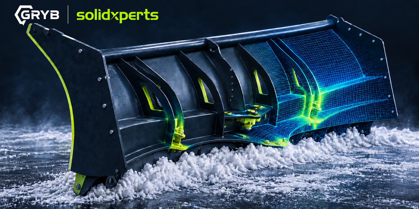
GRYB uses SOLIDWORKS Simulation to identify critical stress areas, validate structural performance and optimize heavy equipment attachments before manufacturing. By replacing part of its physical prototyping and destructive testing process with finite element analysis, the company can develop lighter, stronger products, take on more custom projects and move toward production with greater confidence.

That matters when every design must withstand demanding real-world loads. Choosing the wrong material thickness can create two costly problems: an underdesigned product that may fail, or an overdesigned product that uses more steel, weighs more and costs more than necessary.

In this customer story, GRYB explains how simulation became a core part of its engineering process and helped turn previously impractical projects into viable products.

At a glance: What did SOLIDWORKS Simulation change for GRYB?

SOLIDWORKS Simulation gave GRYB’s engineering team a practical way to predict structural behaviour before building a physical prototype. The team can now locate high-stress zones, compare design decisions, select appropriate materials and thicknesses, review displacement and factor of safety, and document its analysis. This reduces unnecessary prototypes, supports product optimization and shortens the path from concept to manufacturing.

Who is GRYB?

GRYB is a manufacturer of attachments for heavy machinery, including equipment for excavators, loaders and other demanding applications. Founded in 2007, the company has grown from a two-person operation into an international organization whose brand is represented in 20 countries, according to the GRYB website.

Its products serve industries such as construction, excavation, demolition, recycling, material handling and snow removal. Across these applications, GRYB’s goal is consistent: deliver complete solutions that are robust, safe and suited to the customer’s operating requirements.

The company began using SOLIDWORKS Simulation early in its development. According to the webinar, its first use dates back to approximately 2009. Simulation therefore became part of GRYB’s product validation process as the organization and its product catalogue expanded.
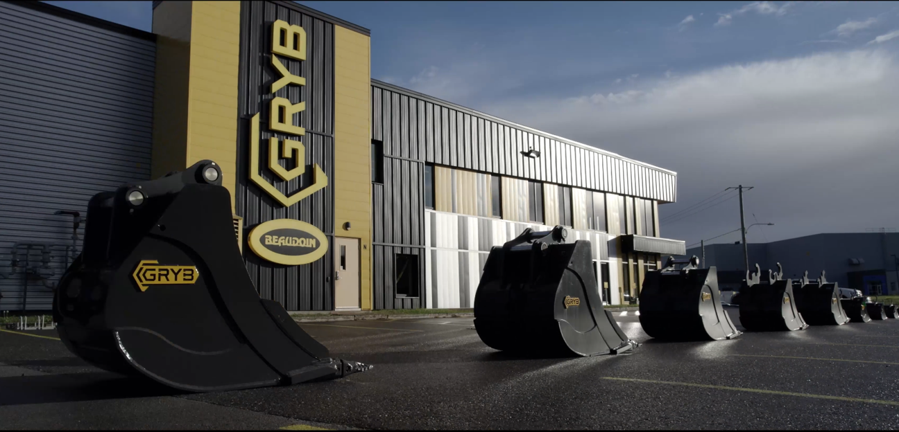
GRYB HQ
Image 1 : GRYB HQ

What engineering challenges did GRYB face before simulation?

Before adopting simulation, GRYB found it difficult to determine exactly where real stresses would concentrate in a product. That uncertainty affected several design decisions:

  • Where should material be reinforced?

  • Which steel grade should be used in each area?

  • How thick should each component be?

  • Which geometry creates the best balance of strength and weight?

  • Will the design perform as expected under its intended load cases?

Without reliable virtual insight, optimization was slower and more expensive. Physical prototypes and destructive tests consumed material, labour and machine time. If a test revealed a problem, the team had to revise the design, manufacture another prototype and test again.

The alternative was often to design conservatively. Adding material may lower perceived risk, but overdesign can increase product weight, material consumption, manufacturing costs and operating demands. It can also hide the real behaviour of the structure instead of addressing the critical load path.

Why are physical prototypes alone not enough?

Physical testing remains important, especially for final validation, certification and complex real-world behaviour. The limitation is that a prototype usually shows what happened, while simulation can provide more insight into where and why it happened.

Finite element analysis can visualize stress, strain and displacement throughout a structure. Engineers can inspect internal load paths and compare design variants before committing to new material and fabrication.

For one-off or highly customized attachments, building several prototypes may be commercially unrealistic. Virtual testing gives the engineering team a way to evaluate those projects earlier and determine whether a proposed design is viable.

How does SOLIDWORKS Simulation help validate a design?

SOLIDWORKS Simulation is a structural analysis solution that uses finite element analysis, or FEA, to predict how a CAD model will respond to loads, restraints and material properties. Because it is integrated into the SOLIDWORKS design environment, engineers can evaluate a model without rebuilding it in a separate interface.

A typical structural study follows these steps:

  1. Define the purpose of the analysis and the expected failure modes.

  2. Simplify the CAD model while preserving structural behaviour.

  3. Confirm the material properties.

  4. Apply fixtures, contacts, connectors and external loads.

  5. Create an appropriate finite element mesh.

  6. Solve the study and review stress, displacement and other results.

  7. Check assumptions, convergence and factor of safety.

  8. Modify the design and compare the new results.

  9. Document the setup, results and engineering conclusions.

The software performs the calculations, but engineering judgment remains essential. A result is only meaningful when the materials, restraints, contacts, loads and modelling assumptions represent the real application closely enough for the decision being made.

Case study: Validating a directional snow blade

The webinar demonstrates a finite element analysis performed on a directional snow blade developed by GRYB. This product experiences significant forces as it moves snow and changes orientation. Its pivots, welded structures and load-bearing components must transfer those forces safely.

The purpose of the study was to verify that the product would deliver the required structural performance under a defined loading scenario.
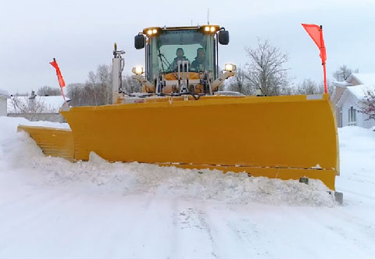
GRYB Directionnal snow blade
Image 2: GRYB Directionnal snow blade

Step 1: Simplify the model

GRYB supplied a simplified 3D model for the analysis. This is a key simulation practice. Running an analysis on every manufacturing detail can add computational cost without improving the answer.

Small cosmetic features, non-structural components and geometry far from the area of interest may be removed when they do not materially affect stiffness or load transfer. The goal is not to create the most detailed model possible. It is to create the simplest model that still represents the relevant physical behaviour.

Model simplification can:

  • reduce meshing and solving time;

  • avoid unnecessary mesh complexity;

  • make contacts and boundary conditions easier to review;

  • help engineers focus on the critical parts of the structure.

Training and experience are important here. Removing the wrong feature can distort stiffness or eliminate a local stress concentration that matters.

Step 2: Transfer and verify materials

Because SOLIDWORKS Simulation is integrated with SOLIDWORKS Design, material assignments from the CAD model can support the study setup. In the webinar example, much of the blade structure uses 44W structural steel, with some exceptions.

Engineers must still verify that the material model and properties match the real product. Yield strength, elastic modulus and other properties directly affect stress interpretation, deformation and factor-of-safety calculations.

Step 3: Apply realistic boundary conditions

The demonstration includes a fixed hinge condition applied to cylindrical faces. Boundary conditions tell the solver how the model is supported and how it can move.

An overly rigid fixture can create artificial stress, while an underconstrained model may move unrealistically or fail to solve. Visual feedback in the software helps users understand the degrees of freedom removed by each restraint, but the setup must still reflect the real mounting condition.

Step 4: Apply the load case

The team then applies a load representing the operating condition to be evaluated. For a directional blade, different positions and loading directions may create different structural responses. A complete validation plan may therefore require more than one load case.

Each case should answer a specific engineering question. For example:

  • What happens under the expected working load?

  • Which orientation creates the highest stress?

  • How does an offset load affect the frame?

  • What happens at the pivots, bolts and welds?

  • Does displacement remain within an acceptable limit?
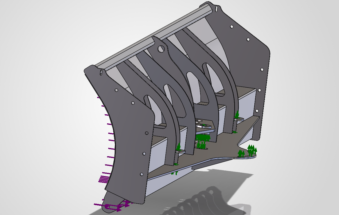
Simplified 3Dmodel with applied conditions

Step 5: Interpret stress, displacement and safety factor

Once solved, the study can display an exaggerated deformation animation that makes the overall structural behaviour easier to understand. Engineers can also review:

  • von Mises stress;

  • strain;

  • displacement;

  • reaction forces;

  • forces in bolts or connectors;

  • weld forces;

  • factor of safety.

These plots help identify risk areas and guide design changes. A single maximum value should not be accepted blindly. Engineers should determine whether the result is physically meaningful, caused by an idealized singularity or sensitive to mesh density and boundary conditions.
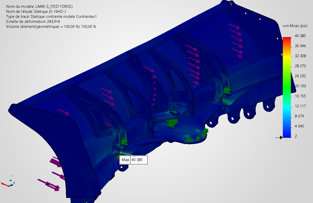
Stress results obtained after the calculations
Image 4: Stress results obtained after the calculations

What benefits did GRYB gain from SOLIDWORKS Simulation?

1. More targeted structural reinforcement

Simulation helps GRYB identify critical zones instead of adding material throughout a product. Reinforcement can be placed where the load path and stress results show it is needed.

2. Lighter and more robust products

Strength and weight do not always need to move in the same direction. By removing unnecessary material from low-stress areas and improving high-risk zones, engineers can pursue a lighter design without sacrificing required performance.

3. Fewer physical prototypes

Virtual testing allows the team to reject weak concepts and improve promising ones before fabrication. Physical testing can then focus on a more mature design, reducing avoidable prototype iterations.

4. Lower long-term material costs

Material optimization can reduce steel consumption across production volumes. Even modest improvements per unit may become meaningful when applied repeatedly.

5. Faster design decisions

Engineers can compare variants inside the CAD workflow and evaluate the effect of changing geometry, thickness or material. This supports shorter design cycles and a faster path to market.

6. Greater confidence in custom projects

GRYB reports that simulation made many customer-specific, one-off projects possible. When repeated physical prototypes are not practical, virtual validation provides evidence that supports the engineering decision.

7. Clearer documentation

SOLIDWORKS Simulation can generate a report that compiles study inputs and results in a Word document. The report does not replace engineering review, but it saves time and creates a useful record for collaboration, design reviews and project files.

Does simulation eliminate physical testing?

No. Simulation reduces dependence on physical prototypes, but it does not automatically eliminate testing. The best product development process uses virtual and physical validation together.

Simulation is especially valuable for screening concepts, locating critical areas, comparing alternatives and understanding structural behaviour. Physical tests remain valuable for confirming model assumptions, capturing manufacturing variability, validating complex contacts and measuring behaviour that is difficult to represent accurately.

Correlation between simulated and measured results improves confidence in future analyses. As a company builds this knowledge, simulation becomes more predictive and more useful earlier in the design process.

Why does SOLIDWORKS integration matter?

SOLIDWORKS states that its Simulation tools are embedded in the SOLIDWORKS Design environment. This integration reduces friction between CAD changes and engineering analysis.

For designers and engineers, that means they can:

  • work with familiar geometry and commands;

  • reuse CAD materials and configurations;

  • evaluate changes earlier in the design process;

  • iterate without repeatedly exporting and importing models;

  • keep design and simulation data more closely connected.

This accessibility supports simulation-driven design, where analysis informs decisions throughout development instead of appearing only as a final check.

What role does simulation training play?

Software alone does not guarantee trustworthy results. Analysts must understand finite element principles, model simplification, contacts, fixtures, meshing and result interpretation.

The GRYB example reflects several simulation best practices, including simplifying the model and clearly defining its constraints. Formal training helps users understand not only which commands to select, but why a particular setup is appropriate and how to recognize a misleading result.

The official SOLIDWORKS Simulation training covers the FEA process from meshing through result evaluation, including linear stress analysis, contact and recommended practices.

If you don’t have an engineer, you can create the initial finite element analysis yourself to save on costs, then have a qualified expert verify and sign it. This approach allows you to reduce expenses by only paying for the expert’s validation time.

A practical checklist for simulation-driven design

Before approving a design based on FEA, ask:

  • Is the engineering question clearly defined?

  • Is the selected study type appropriate for the expected behaviour?

  • Does the simplified geometry preserve stiffness and load paths?

  • Are all materials and their properties accurate?

  • Do fixtures represent the real supports without overconstraining the model?

  • Are loads based on realistic operating conditions?

  • Have relevant contacts, bolts and welds been represented correctly?

  • Is the mesh refined in critical regions?

  • Has mesh sensitivity or convergence been reviewed?

  • Are peak stresses physically meaningful?

  • Does the factor of safety use the correct material limit and design criteria?

  • Have the assumptions and conclusions been documented?

  • Is physical testing or correlation still required?

From trial and error to informed engineering decisions

GRYB’s experience shows that simulation is most valuable when it becomes part of the design process, not simply a final approval step. The technology helped the company locate structural risks, optimize materials, reduce unnecessary prototype cycles and approach custom projects with greater confidence.

The larger lesson applies well beyond heavy equipment. When engineers can predict how a design will behave before manufacturing, they can make faster and better-supported decisions about geometry, materials, cost and performance.

Want to explore how SOLIDWORKS Simulation could fit your product development process? Contact our team to discuss your designs, validation challenges and simulation training needs.

FAQ

What is SOLIDWORKS Simulation?

SOLIDWORKS Simulation is a portfolio of analysis tools integrated into SOLIDWORKS Design. It uses finite element analysis to predict structural response and help engineers validate and optimize CAD designs before manufacturing.

How can simulation reduce prototyping costs?

Simulation allows engineers to identify weak concepts, locate stress concentrations and compare design alternatives virtually. This can reduce the number of physical prototype iterations and focus testing on more mature designs.

What results can SOLIDWORKS Simulation calculate?

Depending on the study and model, results can include stress, strain, displacement, reaction forces, connector loads, weld forces and factor of safety.

Can SOLIDWORKS Simulation help reduce product weight?

Yes. Engineers can use stress and displacement results to remove unnecessary material from low-demand areas and reinforce critical zones, subject to manufacturing and safety requirements.

Is finite element analysis accurate?

FEA can provide valuable predictions when the geometry, material properties, mesh, contacts, loads and restraints represent the real system appropriately. Accuracy depends on both the model and the analyst’s engineering judgment.

Does SOLIDWORKS Simulation replace destructive testing?

Not in every case. It can reduce the number of destructive tests and improve the design before testing, but physical validation may still be required for correlation, certification or complex real-world behaviour.

Can simulation support one-off custom products?

Yes. Virtual analysis is particularly useful when a project volume cannot justify several physical prototypes. It gives engineers a structured way to evaluate a custom design before fabrication.



Chung Ping Lu, eng.

Chung Ping Lu, eng.

Senior Technical Representative

X_green_halo

Any questions? Need help? Ask one of our experts.

Whether you’re ready to get started or just have a few more questions, you can contact us toll-free:

    Onyx GF: When Color Becomes a Function in 3D Printing

    BLOG

    Onyx GF: When Color Becomes a Function in 3D Printing

    [techtips_featured_image_shortcode]

    In an industrial environment, color is rarely chosen for aesthetic reasons alone.

    A red tool, a blue jig, or a green part can instantly communicate information: which machine the tool belongs to, which vehicle model it is intended for, where it should be used, or which operation needs to be performed.

    This use of color is part of a broader visual management approach, particularly common in production environments that apply Lean Manufacturing principles.

    The idea is simple: if information can be understood at a glance, no one needs to search for it.

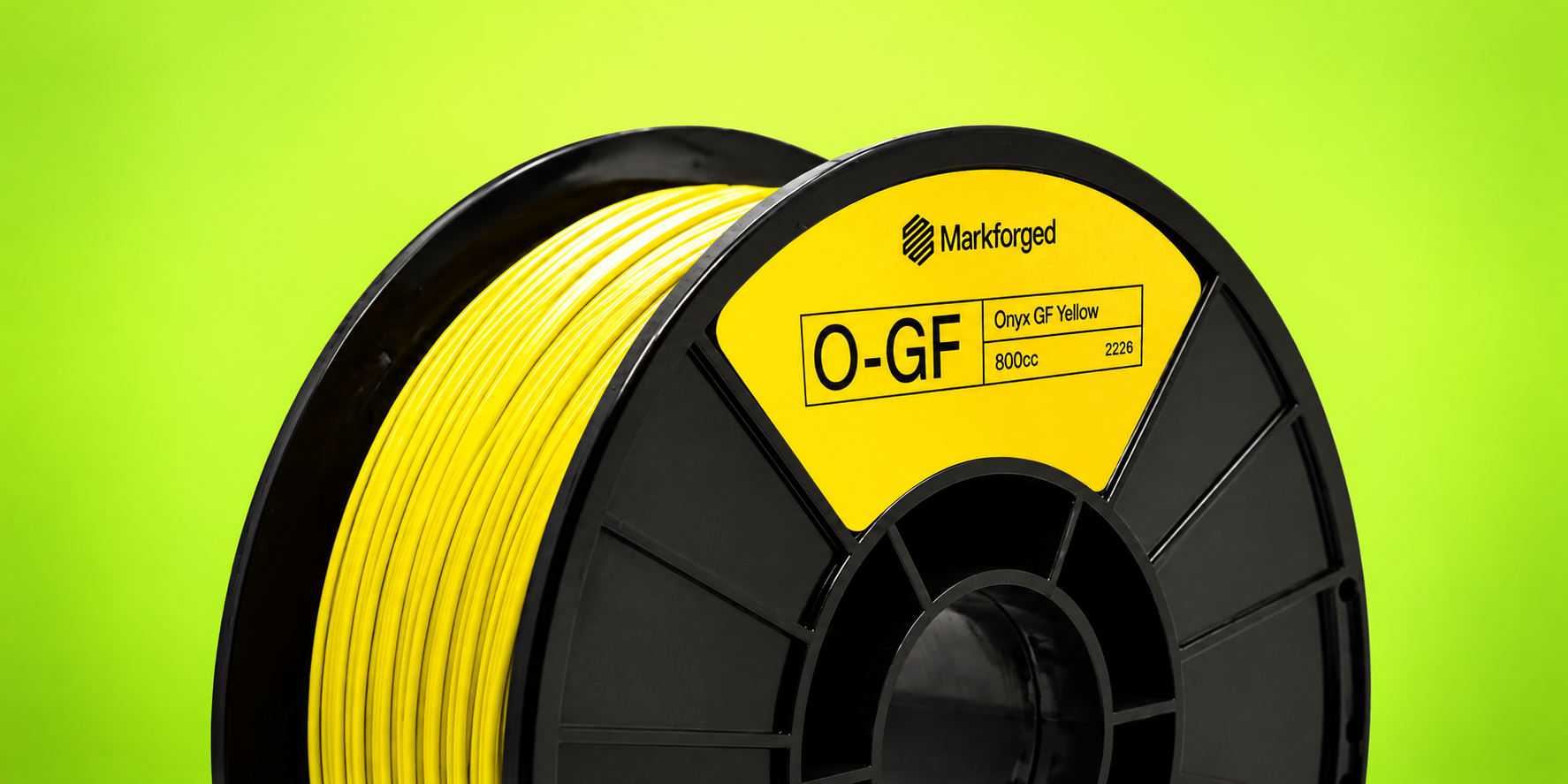
    This is precisely where 3D printing takes on a new dimension with the arrival of Onyx GF, Markforged’s new glass fiber-reinforced nylon, available in several colors.

    Color as a Production Tool

    Using colors to quickly identify tools or equipment is nothing new.

    For example, in the aerospace industry, for example, precision fastener manufacturer M.S. Aerospace uses interchangeable aluminum trays that are color-coded according to the dimensions of the parts they are designed to hold [1]. The goal is not to make the shop floor more visually appealing: color simply helps operators identify the right equipment more quickly.

    A similar approach can be found at PalletOne, an American pallet manufacturer. As part of its Lean initiative, the company assigned each machine its own set of color-coded tools. A blue tool placed near a green machine immediately indicates that it is probably out of place. This organization improves visibility and makes tools easier to track [2].

    In both cases, color becomes a form of information.

    As a result, that information can deliver very tangible value: reducing errors, accelerating an operation, or simply preventing time from being wasted searching for the right tool.

    5S: Making the Workplace Visual

    More broadly, this approach fits directly into the 5S philosophy, a workplace organization method associated with Lean Manufacturing and visual control [3].

    The five steps are often presented by their Japanese names, English translations, and French equivalents:

    Japanese English
    Seiri Sort
    Seiton Set in Order
    Seiso Shine
    Seiketsu Standardize
    Shitsuke Sustain
    • Seiri means eliminating what is not necessary.
    • Seiton means organizing what remains so that every item has a clearly defined place.
    • Seiso adds cleaning and workplace inspection.
    • Seiketsu turns this organization into a standard.
    • Finally, Shitsuke means sustaining these practices over time.

    However, the principle behind 5S goes beyond simply keeping a workshop clean. It is about creating an environment where abnormalities and errors become visible.

    That is where color becomes particularly valuable.

    If color makes it possible to identify a tool immediately, it can become part of the visual control system itself.

    When a Few Millimeters Make All the Difference

    A recent example illustrates this approach particularly well.

    At Subaru of Indiana Automotive (SIA), several vehicle models are produced on the same line. Some of the jigs used for these different models can have very similar geometries, with differences of only a few millimeters.

    In an environment where tools are handled and reused many times during a shift, selecting the wrong jig can lead to an error, rework, or lost time.

    To address this challenge, SIA integrated color coding into its tooling so that the correct jig could be identified immediately.

    The problem was that ABS-printed parts could provide the desired color, but not the durability required for repeated use on an automotive production line.

    This is where Onyx GF comes into its own.

    SIA uses colored Onyx GF tooling for applications ranging from positioning jigs to more robust assembly fixtures. Color differentiates the tools, while the material maintains the mechanical performance required for production use.

    As a result, color is therefore no longer a finish added after manufacturing.

    It becomes part of the part’s function.

    Onyx GF: Where Color Meets Industrial 3D Printing

    With this challenge in mind, Markforged developed Onyx GF.

    Introduced in 2026, Onyx GF is a short glass fiber-reinforced nylon available in six colors: red, yellow, blue, green, gray, and white. The material is designed for industrial applications where color can support visual management, safety, or error prevention.

    The benefits are particularly clear for jigs, fixtures, and production tooling.

    In practical terms, imagine a company that uses several nearly identical jigs for different product variants.

    Instead of having to read a reference engraved on each part, an operator can associate:

    • One color with a model
    • Another with an operation
    • Another with a production area
    • A color with a level of criticality

    Geometry remains important, but identification becomes instantaneous.

    Furthermore, this approach also aligns with the principle of poka-yoke, or mistake-proofing: using product or process design to reduce the possibility of an error occurring.

    From Filament to Production Tool

    In this context, one of the main advantages of 3D printing in this context is the ability to quickly produce tools tailored to a specific application.

    Moreover, a jig does not need to be mass-produced to be cost-effective. A single part or a few units may already justify the use of additive manufacturing when traditional tooling would require more time or resources.

    With Onyx GF, this flexibility now comes with visual information built directly into the part.

    Potential applications include:

    • Assembly jigs differentiated by model
    • Fixtures identified by workstation
    • Tool holders associated with a specific machine
    • Replacement parts identified by function
    • Tooling intended for environments where FOD management is important
    • Safety components that require quick visual identification

    Color can even distinguish several versions of the same part without requiring any change to its geometry.

    A Color That Eliminates an Additional Step

    Traditionally, when a printed part needed to be visually identified, several solutions were available: paint, labels, markings, or engraving.

    These methods can work, but they add another step to the manufacturing process.

    By contrast, with a colored material, the information is built directly into the part during printing.

    This is particularly valuable in a production environment, where every additional step can become a source of variation or maintenance.

    The approach is even more relevant when the part is handled regularly. Color embedded in the material does not depend on a label that could peel off or paint that could wear away.

    What If the Part Also Needs to Be Strong?

    This is where the comparison with traditional colored plastics becomes interesting.

    However, color alone is not enough for an industrial application. A production jig must withstand handling, repeated contact, and the specific stresses of its environment.

    Onyx GF uses a nylon matrix reinforced with short glass fibers. Published data indicates a flexural strength of 88.2 MPa and a flexural modulus of 2.4 GPa. The material can also be reinforced with Continuous Carbon Fiber for applications requiring greater structural performance.

    This positions Onyx GF not simply as a new way to produce colored parts, but as a material designed for functional industrial applications.

    Onyx GF or Onyx?

    The comparison with standard Onyx is particularly interesting.

    Standard Onyx is a nylon reinforced with chopped carbon fiber. Markforged reports a flexural strength of 71 MPa and a flexural modulus of approximately 3.0 GPa for this material [4].

    Property Onyx Onyx GF
    Reinforcement Chopped carbon fiber Short glass fibers
    Colors Black Six colors
    Flexural strength 71 MPa 88.2 MPa
    Flexural modulus ~3.0 GPa 2.4 GPa
    Continuous fiber reinforcement Yes Yes, with Continuous Carbon Fiber
    Typical applications Engineering parts and tooling Color-coded tooling, visual management, and industrial applications

    Of course, these values should be compared with caution, since testing conditions and print parameters can influence the final properties of a part.

    The key is therefore not to determine which material is “better,” but to choose the one that best suits the application.

    In other words, Onyx remains an excellent choice when color does not provide functional value, while Onyx GF becomes particularly valuable when visual identification is part of the requirement.

    What Do You Need to Print With Onyx GF?

    At launch, Onyx GF is compatible with the Markforged FX10 and FX20 printers. Because the material contains glass fibers, it also requires a Plastic Hardened Nozzle.

    Onyx GF can also be combined with Continuous Carbon Fiber for applications requiring greater structural strength.

    However, compatibility is expected to evolve. The material has only just entered the market, and information published by Mark3D already indicates that support for additional Markforged platforms is planned in the near future.

    Therefore, it will be worth following its development over the coming months.

    A New Way to Think About Tooling

    Ultimately, the arrival of Onyx GF illustrates an interesting trend in industrial additive manufacturing: the value of a part is not limited to its mechanical properties.

    Its color, ease of identification, role in a 5S process, or ability to prevent an error can be just as important.

    For a company already 3D printing its jigs and fixtures, switching to a colored material may seem like a small change.

    Operationally, however, it can transform how tools are organized and used on the production floor.

    And that may be the main advantage of Onyx GF: transforming color into a true function of the part without compromising the requirements of industrial 3D printing.


    Lilian

    Lilian Beatrix

    Additive Manufacturing Specialist

    X_green_halo

    Any questions? Need help? Ask one of our experts.

    Whether you’re ready to get started or just have a few more questions, you can contact us toll-free:
      How SOLIDWORKS Flow Simulation and Markforged Simulation Helped Optimize a Race Car Part

      BLOG

      How SOLIDWORKS Flow Simulation and Markforged Simulation Helped Optimize a Race Car Part

      [techtips_featured_image_shortcode]

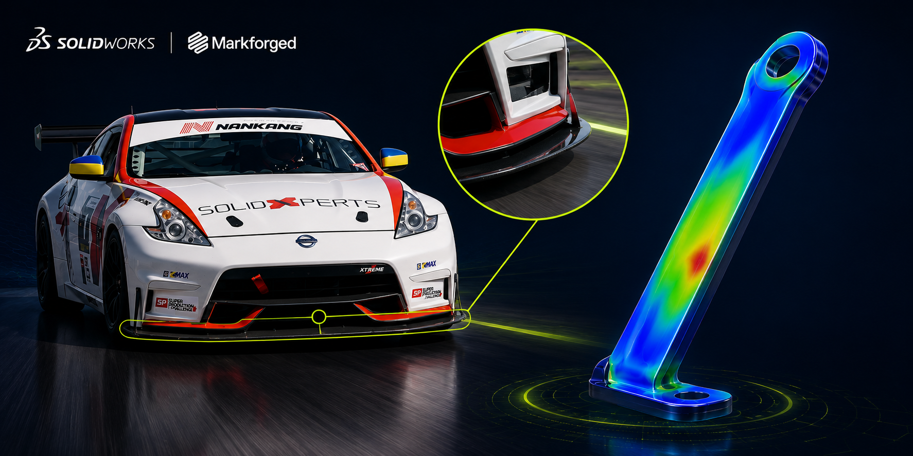
      In this project, SOLIDWORKS Flow Simulation and Markforged Simulation were used to optimize a reinforcement bracket for a race car before it was manufactured. Aerodynamic simulation helped determine the loads acting on the part, while Eiger was used to optimize its print orientation, infill, and continuous carbon fiber reinforcement. The final 3D-printed part achieved a worst case safety factor of 2.18 while keeping material usage and manufacturing costs under control.

      From the Racetrack to Additive Manufacturing

      A difference in handling between the left and right sides of a race car may seem minor. At high speeds, however, it can reveal an important mechanical or aerodynamic issue.

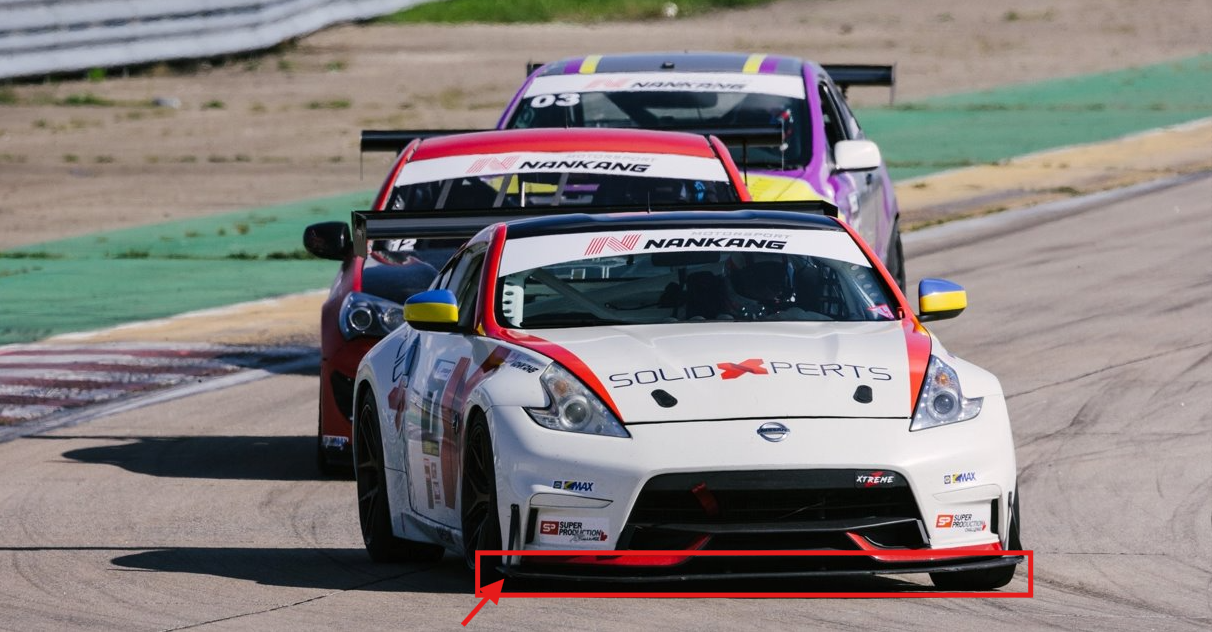
      That is exactly what happened with one of the vehicles sponsored by Solidxperts. The driver noticed a difference in how the car behaved from one side to the other. After several inspections, the team discovered that the splitter, the component located at the front and underneath the vehicle, had partially detached on one side.

      Racetrack to Additive Manufacturing

      A reinforcement bracket was needed to securely hold the splitter in place without negatively affecting the vehicle’s aerodynamics. Since only a small number of vehicles required the part, additive manufacturing offered a fast and cost-effective solution.

      The project followed three main steps:

      1. Optimize the bracket geometry using SOLIDWORKS Flow Simulation.

      2. Determine the loads that the part would need to withstand.

      3. Optimize its print orientation and manufacturing parameters using Markforged Simulation in Eiger.

      Why Simulate a Part Before 3D Printing It?

      Simulation makes it possible to evaluate multiple concepts virtually before spending time and material on physical prototypes. It can help answer practical questions such as:

      • Does the part’s shape increase aerodynamic drag?

      • Will the component withstand the expected loads?

      • Which print orientation provides the best mechanical performance?

      • Where should continuous carbon fiber be added?

      • Can the required safety factor be achieved without unnecessarily increasing cost?

      In this project, simulation created a link between design and manufacturing. The results from the fluid analysis were used to define the structural loads, and the printing parameters were then adjusted based on the stresses acting on the part.

      Step 1: Optimizing Aerodynamics with SOLIDWORKS Flow Simulation

      Defining Realistic Operating Conditions

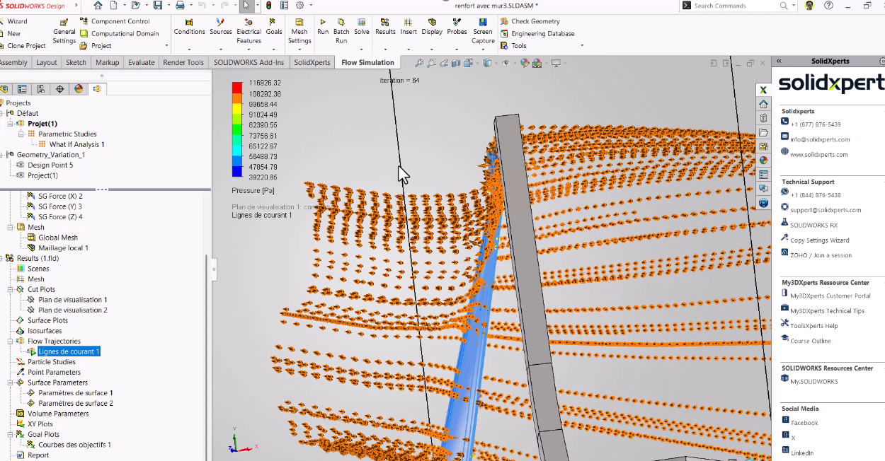
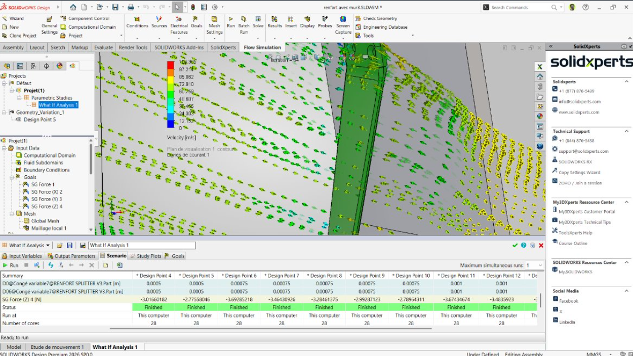
      SOLIDWORKS Flow Simulation is directly integrated into SOLIDWORKS. Its setup tools guide users through the definition of fluids, units, boundary conditions, and simulation goals.

      To reproduce a demanding operating condition, the team simulated a total relative air speed of 300 km/h, representing a vehicle traveling at 200 km/h with a 100 km/h headwind.

      The primary objective was to measure the drag force acting on the reinforcement bracket. This value would later be used as an input load for the structural validation of the part.

      Creating an Appropriate Mesh

      The mesh divides the simulation domain into small cells where the software solves the fluid flow. Local mesh refinement can be applied around surfaces and details that have a greater influence on the results.

      A mesh preview makes it possible to review the setup before running the calculation. This is an important step, since a simulation is only as reliable as the assumptions, boundary conditions, and mesh used to represent the real-world situation.

      Evaluating the Airflow and Measuring Drag

      Once the calculation was complete, flow trajectories made it possible to visually confirm how the air moved around the part. The first configuration produced a drag force of approximately 14 to 15 N.

      To maintain a conservative margin, the team also analyzed the part without considering the beneficial aerodynamic effect of the vehicle body. This more severe scenario produced approximately 20 N of drag, and this value was retained for the next stage of the project.

      Evaluating the Airflow and Measuring Drag

      Automating Geometry Optimization

      A design study can automatically vary several parameters, including:

      • The radius of the leading edge

      • The thickness of the part

      • Its angle

      • Other dimensions that influence the airflow

      Instead of manually modifying and recalculating each version, the software can compare multiple scenarios to identify the geometry that minimizes drag. This approach reduces the number of physical prototypes required and speeds up concept validation.

      Step 2: Turning Simulation Results into Strength Requirements

      Once the bracket geometry had been defined, the next step was to establish the design loads. Three objectives were selected:

      • Withstand an aerodynamic load of 40 N, representing the conservative 20 N drag force multiplied by a factor of two.

      • Support a vertical load of 25 N per screw, for a total of 50 N, representing the weight and forces acting on the splitter.

      • Achieve an overall safety factor greater than 2.

      These conditions were then reproduced in Eiger.

      The upper connection to the vehicle body was modeled as a fixed constraint, while the lower mounting points were represented by supports that allowed certain movements while restricting the required transverse motion.

      Automating Geometry Optimization

      Step 3: Choosing the Best Markforged Print Orientation

      Why Does Print Orientation Affect the Strength of a 3D-Printed Part?

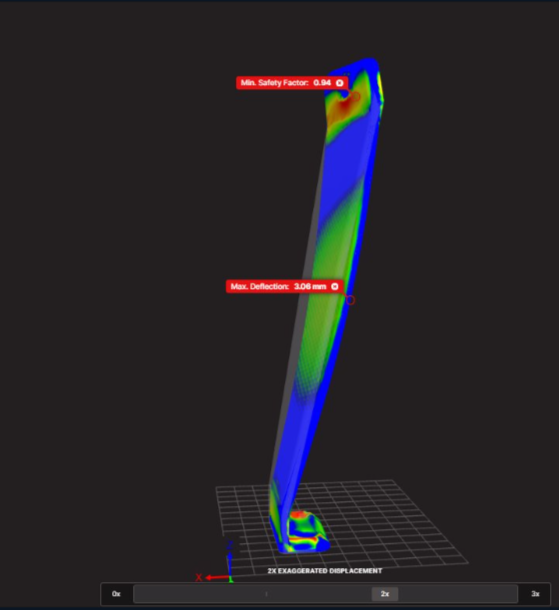
      A 3D-printed part does not have the same mechanical properties in every direction. The material is generally weaker along the Z-axis, which corresponds to the direction in which layers are stacked, due to the nature of interlayer bonding.

      The goal is therefore to orient the part so that its weakest direction is exposed to the lowest stresses.

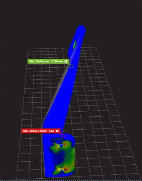
      Two orientations were compared in Eiger:

      Print Orientation

      Safety Factor

      Estimated Cost

      Result

      Vertical

      0.94

      $10.89

      Insufficient strength

      Horizontal

      1.47

      $11.06

      56% increase in safety factor

      The horizontal orientation increased the safety factor by 56%, while the estimated cost increased by only about 1.5%. It was therefore selected as the starting point for the final optimization.

      Why Does Print Orientation Affect the Strength of a 3D-Printed Part?

      Why Does Print Orientation Affect the Strength of a 3D-Printed Part?!

      The costs presented in this case study are specific to the project and are primarily intended to compare different configurations. Actual costs may vary depending on the material, machine, print settings, and production conditions.

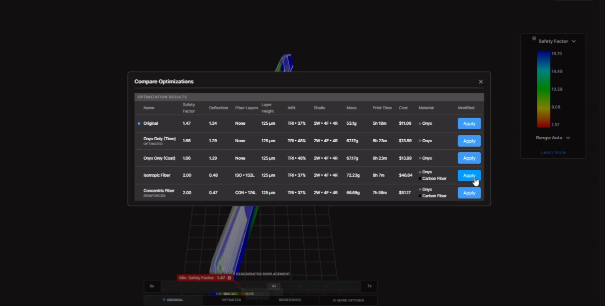
      Step 4: Optimizing Infill and Continuous Carbon Fiber Reinforcement

      After selecting the print orientation, the team compared several manufacturing parameters, including:

      • Infill density and pattern

      • Number of walls

      • Number of floor and roof layers

      • Placement of continuous fiber

      • Total material usage

      Eiger’s optimization capabilities proposed a continuous carbon fiber-reinforced configuration capable of exceeding the target safety factor.

      The automatically generated configuration was then refined further. Fiber layers that were initially adjacent to one another were separated by a layer of Onyx, as the bonding between Onyx and fiber can be preferable to stacking fiber directly against fiber.

      The fiber groups were also distributed toward the upper and lower regions of the part to create a structure similar to a sandwich panel.

      This arrangement improves stiffness while placing reinforcement where it provides the greatest benefit.

      Optimizing Infill and Continuous Carbon Fiber Reinforcement

      The Result: A Part Validated Before Manufacturing

      The final configuration achieved a safety factor of 2.18, exceeding the original target of 2.

      The estimated manufacturing cost remained around $30, while still being lower than some of the configurations proposed during the optimization process.

      The workflow made it possible to develop a reinforcement bracket that met the project’s three main objectives:

      • Minimize aerodynamic impact

      • Withstand the loads experienced on the racetrack

      • Reduce both manufacturing costs and the number of physical iterations

      What Are the Benefits of Combining SOLIDWORKS and Markforged Simulation?

      Using SOLIDWORKS Flow Simulation together with Markforged Simulation creates a digital workflow that connects design, validation, and manufacturing.

      This approach makes it possible to:

      • Measure realistic loads instead of relying on arbitrary estimates

      • Quickly compare multiple geometries

      • Reduce the number of physical prototypes

      • Select a print orientation based on mechanical performance

      • Strategically place continuous fiber reinforcement

      • Balance cost, print time, and part performance

      • Accelerate the production of low-volume parts

      For automotive, industrial, and manufacturing applications, this workflow helps engineers make better decisions before the first physical part is even printed.

      From Analysis to a Production-Ready Part

      A high-performance 3D-printed part depends on more than its geometry. Its performance is also influenced by the actual loads it experiences, its print orientation, the selected material, and the placement of reinforcement.

      The experts at Solidxperts can help you integrate SOLIDWORKS Flow Simulation and Markforged solutions into your product development process. By validating concepts earlier, you can reduce iterations and manufacture parts that are better suited to their real-world operating environment.

      From Analysis to a Production-Ready Part

      A high-performance 3D-printed part depends on more than its geometry. Its performance is also influenced by the actual loads it experiences, its print orientation, the selected material, and the placement of reinforcement.

      The experts at Solidxperts can help you integrate SOLIDWORKS Flow Simulation and Markforged solutions into your product development process. By validating concepts earlier, you can reduce iterations and manufacture parts that are better suited to their real-world operating environment.

      Contact our experts to discuss your next simulation or additive manufacturing project.

      FAQ

      What Is SOLIDWORKS Flow Simulation?

      SOLIDWORKS Flow Simulation is a computational fluid dynamics, or CFD, tool integrated into SOLIDWORKS. It can be used to simulate the flow of liquids and gases, visualize flow trajectories, and calculate results such as pressure, temperature, and drag force.

      What Is Markforged Simulation in Eiger Used For?

      Markforged Simulation in Eiger is used to evaluate the mechanical performance of a part before it is printed. It makes it possible to compare print orientations, infill parameters, and reinforcement strategies in order to achieve a target level of performance while controlling manufacturing costs.

      Why Can a Horizontally Printed Part Be Stronger?

      The strength of a 3D-printed part depends on the direction of its layers. The Z-axis can be more vulnerable to interlayer separation. A horizontal orientation may place the primary loads within the plane of the printed layers, where the part can provide better mechanical performance.

      What Safety Factor Should Be Used for a 3D-Printed Part?

      The appropriate safety factor depends on the application, loads, material, operating environment, and consequences of failure. In this automotive project, the target was a safety factor greater than 2, and the final design achieved 2.18.

      Critical parts should always be validated according to the standards and operating conditions applicable to their intended use.

      Is Continuous Carbon Fiber Always Necessary?

      No. The need for continuous fiber depends on the loads acting on the part and the required level of stiffness and strength.

      Simulation can help determine whether Onyx alone is sufficient or whether continuous fiber reinforcement is required. It can also help identify where that reinforcement will provide the greatest benefit.

      Can Simulation Reduce Prototyping Costs?

      Yes. By comparing multiple geometries and printing parameters virtually, it is possible to eliminate insufficient concepts before manufacturing them.

      This can reduce material consumption, machine time, and the number of physical prototypes required during development.


      Lilian

      Lilian Beatrix

      Additive Manufacturing Specialist

      X_green_halo

      Any questions? Need help? Ask one of our experts.

      Whether you’re ready to get started or just have a few more questions, you can contact us toll-free:
        From CAD to Wax: How MJP 3D Printing Is Transforming Jewelry Manufacturing

        BLOG

        From CAD to Wax: How MJP 3D Printing Is Transforming Jewelry Manufacturing

        [techtips_featured_image_shortcode]

        A new piece of jewelry can begin with just a few lines in a CAD software. But before it becomes a piece made of gold, silver, or another precious metal, that design still has to go through an essential step: becoming a physical model precise enough to be integrated into the casting process.

        And this is where things get interesting.

        What happens when a design is particularly complex? When a customer requests a customization? When several variations of the same model need to be produced? Or when a model needs to be manufactured quickly without creating new tooling?

        Additive manufacturing offers a direct answer: produce the wax model directly from the digital file.

        This is precisely the application for which 3D Systems’ MultiJet Printing (MJP) solutions have been developed. By combining a printer designed for jewelry models, dedicated wax materials, and 3D Sprint preparation software, the workflow can move directly from digital design to a model intended for the lost-wax casting process.

        When Every Detail Matters

        In jewelry manufacturing, a few fractions of a millimeter can make a significant difference.

        A model may contain fine details, sharp edges, organic shapes, or complex geometries. For the final result to remain faithful to the original design, the wax model must reproduce these characteristics accurately.

        The ProJet MJP 2500W Plus was specifically developed to produce wax casting patterns for jewelry applications. It uses VisiJet 100% wax materials designed to produce models faithful to the CAD design, with sharp edges and precise detail definition. 3D Systems also indicates that certain materials are designed to melt like traditional casting waxes and burn out without ash residue.

        The MJP 300W Plus offers several print modes designed to meet different production requirements. Its Premium ZHD mode uses an 8 μm layer thickness, while the QHD and XHD modes use 14.1 μm and 16 μm layer thicknesses, respectively. The system’s stated typical dimensional accuracy is ±0.0508 mm per 25.4 mm of part dimension.

        The MJP 300W Plus also offers a QHD mode with a stated resolution of 2,400 × 1,800 × 1,800 dpi. These different print modes make it possible to adapt the process to the desired balance between detail, surface quality, and productivity.

        The goal is therefore not simply to produce a model that resembles the original design. It is to reproduce the characteristics of the digital model as accurately as possible before integrating it into the casting process.

        Why Print Directly in Wax?

        The answer lies in the workflow.

        When a model is produced using traditional methods, several intermediate steps may be required. Depending on the application, creating a master model and a mold may also be part of the process.

        3D wax printing offers a different approach: the digital file becomes the direct starting point for manufacturing the physical model.

        CAD model → digital preparation → wax printing → lost-wax casting → final metal part

        This approach makes it possible to produce a physical model directly from the digital design. A modification made to the CAD file can then be prepared for a new print without necessarily having to recreate a master model or mold for every variation.

        This can be particularly interesting for customized jewelry, small production runs, and designs requiring multiple iterations.

        Additive manufacturing does not replace every traditional jewelry manufacturing method. Instead, it offers another way to produce certain models when customization, geometric complexity, or process flexibility are priorities.

        3D Sprint: Connecting Design and Manufacturing

        A precision 3D printer can only produce data that has been properly prepared for manufacturing.

        This is why software plays an essential role in the workflow.

        3D Sprint is 3D Systems’ additive manufacturing preparation and production management software. It is used to prepare digital data and organize models for compatible systems.

        In jewelry applications, the preparation capabilities go beyond simply positioning models on a build platform. On the MJP 300W Plus, sprues and runners can be accessed through the Strut function, facilitating the addition of structures required to prepare certain parts for casting. The software also includes the Surface Enhance function, designed to improve certain surfaces depending on the needs of the model.

        The result is a more cohesive workflow:

        CAD design → preparation in 3D Sprint → MJP printing → wax model → casting

        Digital preparation therefore becomes an integral part of the manufacturing process. The final result depends not only on the printer, but also on how the model is prepared for production.

        One Printer, Multiple Ways to Produce

        Not every jewelry model requires the same balance between resolution, speed, and productivity.

        This is why the MJP 300W Plus offers multiple print modes.

        The XHD mode is designed to balance speed and quality for the production of larger batches.

        The Premium ZHD mode, with an 8 μm layer thickness, is designed to produce highly detailed models, particularly for upward-facing surfaces.

        The QHD mode offers a resolution of 2,400 × 1,800 × 1,800 dpi according to 3D Systems’ specifications.

        This flexibility makes it possible to adapt the process to the model being produced. A highly detailed part may require a different priority than a production run consisting of a large number of models.

        The best configuration is therefore not necessarily the one that maximizes resolution alone. The appropriate mode should be selected based on the required level of detail, geometry, and production volume.

        A Workflow That Evolves with the Design

        Jewelry is an industry where customization plays an important role.

        A model may need to be modified to meet a customer’s requirements. A collection may require several sizes or variations. A new design may need to be tested before being introduced into larger-scale production.

        In these situations, digital manufacturing offers significant flexibility.

        The design can be modified in the CAD file. The new file can then be prepared and printed.

        The ability to move quickly between the physical model and the digital model reduces the distance between design and production.

        The development process becomes more flexible: a design can be tested, modified, and reproduced as the project evolves.

        A Real-World Example: The Narsakka Case Study

        One of the best ways to understand the value of a workflow is to look at what happens in a real production environment.

        Narsakka, a Finnish jewelry company, integrated a 3D Systems wax 3D printing solution to produce models intended for casting.

        According to the case study published by 3D Systems, Narsakka can produce 60 to 100 wax models in just four hours, helping reduce production lead times from several weeks to a few days.

        The company uses the ProJet MJP 2500W with VisiJet M2 CAST material. The workflow also uses soluble and fusible support materials, allowing batch support removal and quick access to models ready for casting.

        The case study also highlights another advantage of a digital workflow: flexibility. Narsakka uses the solution for both larger production batches and more specialized custom jewelry production.

        According to 3D Systems, the company also eliminated the need for master models and rubber molds in its process and reported a 100% success rate for the parts produced as part of the case study. These results should naturally be understood within the specific context of Narsakka’s application and production process, but they clearly illustrate the potential of an integrated digital workflow.

        Why Choose an MJP Solution Over Another Technology?

        Not all 3D printing technologies are designed to meet the same requirements.

        For the production of jewelry models, several factors must be considered simultaneously:

        • accuracy;

        • the ability to reproduce fine details;

        • surface quality;

        • the material being used;

        • compatibility with the casting process;

        • production speed;

        • the amount of post-processing required.

        This is where 3D Systems’ approach becomes particularly interesting. The solution is not limited to a printer.

        It combines an MJP technology designed for jewelry models, wax materials compatible with the casting process, and a software environment that enables files to be prepared for manufacturing.

        For a jewelry manufacturer, this means evaluating the solution as a complete workflow rather than comparing only the resolution or speed of a machine.

        From Digital Design to the Final Piece

        Additive manufacturing does not change the creativity at the heart of jewelry making.

        It changes how certain designs can be transformed into physical models.

        A complex model can be prepared digitally. A customization can be integrated into the CAD file. Multiple variations can be produced. A wax model can then be integrated into the casting process.

        For jewelry professionals in Montreal and across Quebec, MJP 3D printing offers a way to further integrate digital manufacturing into an existing workflow.

        The question is not simply whether a 3D printer can produce a wax model.

        The real question is:

        What could you produce if your digital design could become a precise, repeatable casting pattern directly integrated into your production process?

        With its MJP solutions, VisiJet wax materials, and 3D Sprint software, 3D Systems offers an integrated approach to bringing digital design closer to jewelry manufacturing.

        From CAD to wax. From wax to metal. And from a digital idea to a real piece.


        Lilian

        Lilian Beatrix

        Additive Manufacturing Specialist

        X_green_halo

        Any questions? Need help? Ask one of our experts.

        Whether you’re ready to get started or just have a few more questions, you can contact us toll-free:
          How Additive Manufacturing with Markforged Helped Avoid the Costly Replacement of a Cooler

          BLOG

          How Additive Manufacturing with Markforged Helped Avoid the Costly Replacement of a Cooler

          [techtips_featured_image_shortcode]

          Can you already smell the BBQ?

          Last summer, I went to a store to buy a cooler. I found one at an unbeatable price, but it was missing two retaining pins for the handle.

          That’s when I had an idea.

          Why not design and 3D print them?

          So, I left the store with the cooler, a big smile on my face, and full confidence that I could find a solution in time for the BBQ.

          BBQ Solidxperts
          BBQ Solidxperts x Markforged

          Challenge: A Cooler with Missing Parts

          A BBQ was scheduled just a few days later. I wanted to buy a cooler to keep drinks cold throughout the evening, but my budget was limited.

          I came across a brand-new 45.4 L cooler for the modest price of $15 CAD. The only issue was that it was missing the two pins that secured the handle on one side. Despite searching throughout the store, I was unable to find replacement parts that could be purchased with it.

          Without these pins, the cooler was still usable, but moving it around would have been much less convenient since the handle would not function properly. A comparable new cooler would have cost approximately $50 CAD before taxes. Ordering replacement parts was also an option, but not necessarily the most cost-effective one due to potential shipping costs and delivery delays.

          With a BBQ quickly approaching, I needed a solution that was both effective and fast.

          Evaluating the Options

          Let’s take a quick look at the available options:

          • Purchase a New Cooler : The simplest solution, but also the most expensive unless a significant discount is available.

          • Order the Missing Parts : A viable option, but the total cost could quickly increase due to part pricing, shipping fees, and delivery times.

          • Manufacture the Parts In-House : An ideal solution for a company that has access to a 3D printer and the expertise needed to quickly design replacement parts.

          Considering the tight timeline, the very low production cost, and the minimal effort required to design and print the parts, I chose additive manufacturing.

          Markforged printers can produce durable parts using materials such as onyx, nylon, carbon fiber, fiberglass, and even metal. This makes them an excellent solution for challenges like this one.

          Designing and Printing the Pins

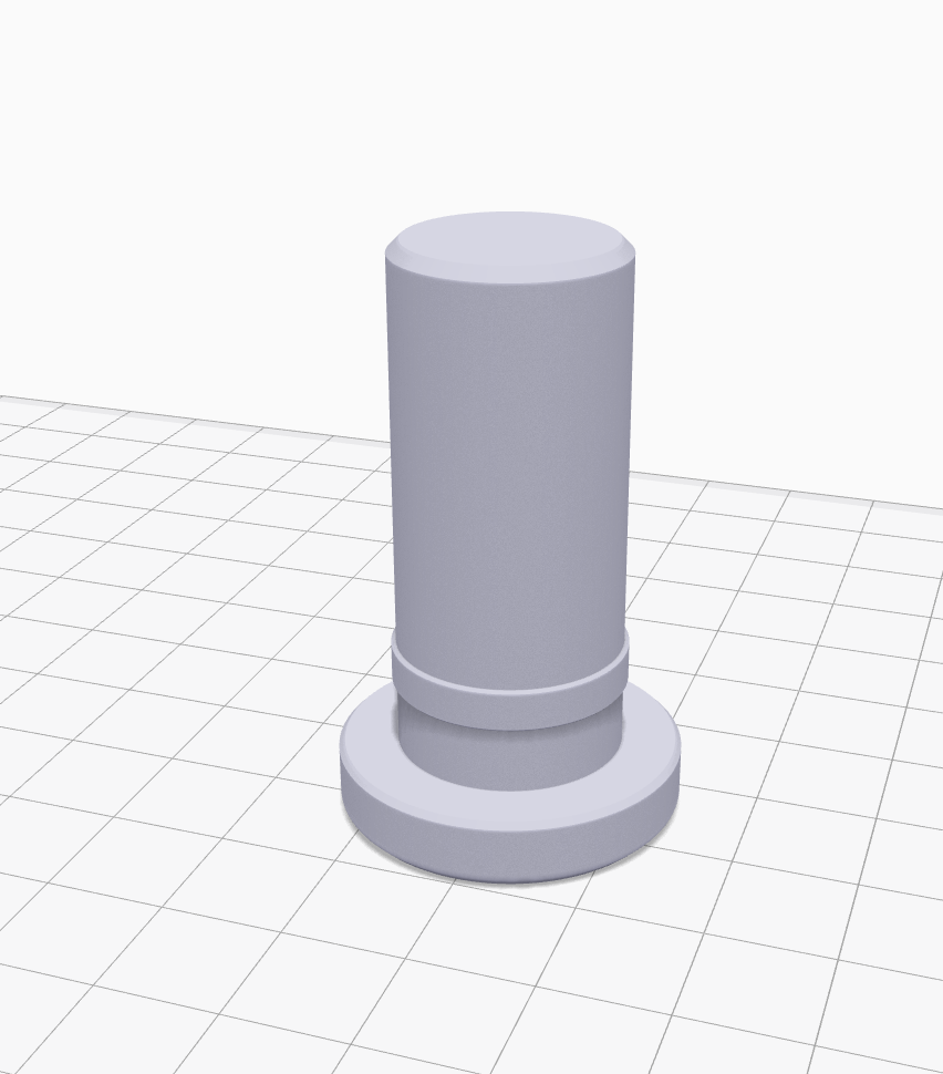
          I brought the cooler to my colleague, Charles-Olivier Provost, and in less than two hours, the problem was solved.

          The process was straightforward. He removed one of the existing pins from the functional side of the handle and measured its dimensions using calipers, including diameter, length, and other key features. Using those measurements, he recreated the part in SOLIDWORKS. The modeling process took only a few minutes.

          Once the model was completed, it was exported to Markforged’s Eiger software to prepare it for printing.

          Pièce dans Eiger
          The modeled part imported into Markforged Eiger.

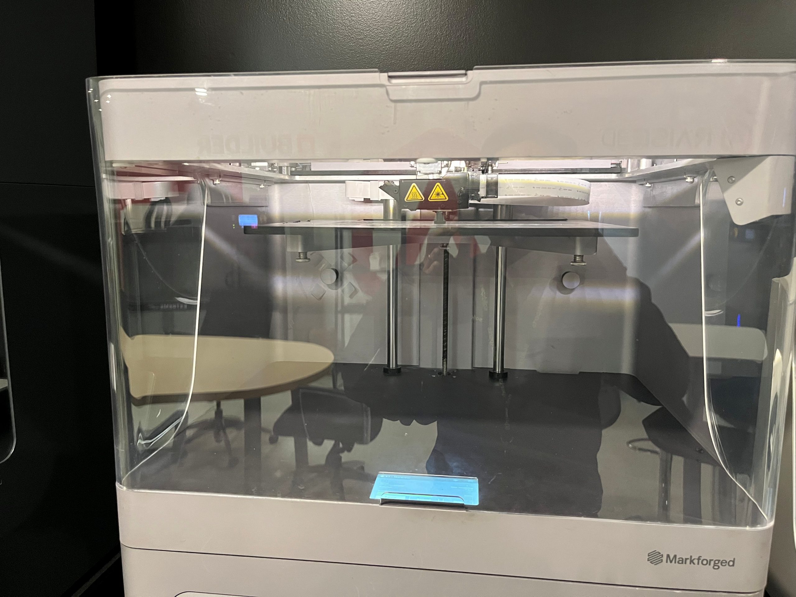
          A few minutes later, the print job was launched on a Markforged X7 printer using an onyx material. In just over an hour, the two replacement parts were ready.

          Impression Markforged
          Launching the print job on the Markforged X7 3D printer.

          Results

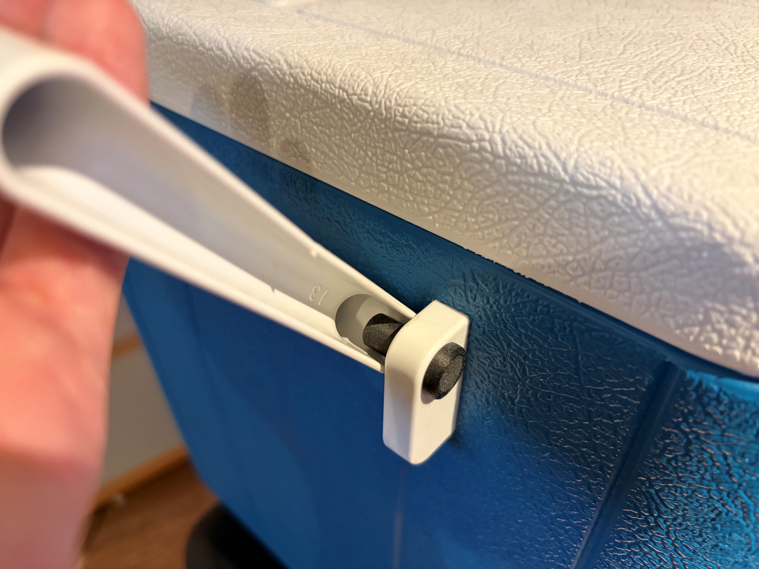
          Once the two parts were printed, they were installed in their respective locations. A few quick tests confirmed that the handle functioned perfectly, just as if the cooler were brand new.

          That was when my colleague told me, “Your cooler is ready.”

          The moment I had been waiting for.

          For me, it was the satisfaction of having made a great purchase while staying within budget and meeting the BBQ deadline. For Charles-Olivier, it was the satisfaction of solving a practical problem using precise measurements, SOLIDWORKS, and his secret weapon: a Markforged 3D printer.

          The savings were significant. The pair of replacement parts cost approximately $1.50 CAD to produce, compared to the potential cost of ordering replacement parts with shipping fees or purchasing a brand-new cooler.

          Pièce finale
          Cooler repaired using a 3D-printed replacement pin (black part).

          How 3D Printing Reduces Costs and Lead Times

          In an industrial setting, the parts involved can represent equipment worth thousands or even tens of thousands of dollars.

          3D printing stands out because of its flexibility and rapid production capabilities. When the availability of a replacement part becomes a challenge and a solution is needed quickly, additive manufacturing truly demonstrates its value.

          Extending the lifespan of products not only helps reduce costs but also contributes to more sustainable and responsible practices.

          To learn more about additive manufacturing and the Markforged solutions offered by SolidXperts, visit: 3D Printing and Scanning Solutions – Solidxperts


          Chung Ping Lu, eng.

          Chung Ping Lu, eng.

          Senior Technical Representative

          X_green_halo

          Any questions? Need help? Ask one of our experts.

          Whether you’re ready to get started or just have a few more questions, you can contact us toll-free:
            Guide: Getting Started with AI in SOLIDWORKS

            BLOG

            Guide: Getting Started with AI in SOLIDWORKS in 2026

            [techtips_featured_image_shortcode]

            Artificial Intelligence is quickly becoming part of everyday engineering workflows, but if you’re a SOLIDWORKS user, the big question is usually:

            “Where do I even start?”

            The good news is that AI in SOLIDWORKS isn’t something separate you need to learn from scratch. It’s already being integrated into the tools you use every day through the 3DEXPERIENCE platform.

            In this guide, we’ll walk through everything you need to get started, step by step:

            • Required software and prerequisites

            • Activating the 3DEXPERIENCE platform

            • Installing the Design with SOLIDWORKS connector

            • Accessing AI tools like the new AI Labs tab

            No fluff, just what you need to get up and running.

            Step 1: Understand What “AI in SOLIDWORKS” Actually Means

            Before jumping into setup, it’s important to clarify something:

            AI in SOLIDWORKS isn’t a single feature. It’s a set of capabilities delivered through the 3DEXPERIENCE platform.

            Today, that includes things like:

            • Design assistance and recommendations

            • Automation of repetitive tasks

            • Data-driven insights

            • Early access tools in Virtual Companions

            In other words, AI is layered into your workflow, not replacing it.

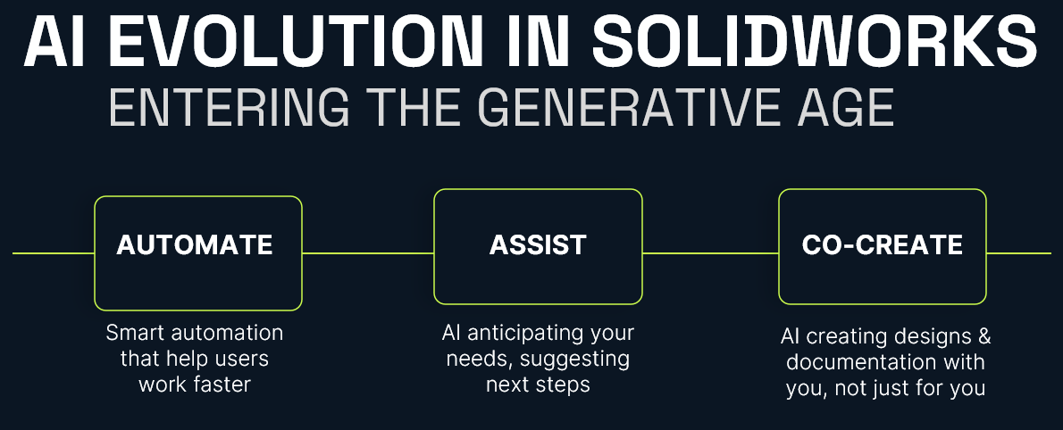
            AI Evolution in SOLIDWORKS

            Step 2: Confirm Your Prerequisites

            Before you can access any AI-driven tools, you’ll need a few key components in place.

            Required Software

            • SOLIDWORKS 2026 (or newer)

            • Active subscription (required for cloud services integration)

            Platform Access

            • A 3DEXPERIENCE platform account

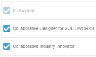
            • Assigned roles (including Collaborative Designer for SOLIDWORKS)

            System Requirements

            • Stable internet connection

            • Admin rights for installation

            • Browser access to the platform

            If you’re missing any of these, that’s your starting point.

            Step 3: Activate the 3DEXPERIENCE Platform

            AI functionality depends on your connection to the 3DEXPERIENCE platform.

            How to Activate:

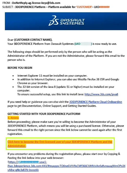
            • Check your welcome email from Dassault Systèmes
            • Click the activation link
            • Set your password and log in
            • Access your platform dashboard

            Once inside, you should see your roles and available apps.

            Still confused? Follow our Getting Started guide:
            Getting Started with the 3DEXPERIENCE Platform

            Step 4: Install the 3DEXPERIENCE Launcher

            Before installing any apps, you’ll need the 3DEXPERIENCE Launcher.

            Steps:

            • Log into your 3DEXPERIENCE platform
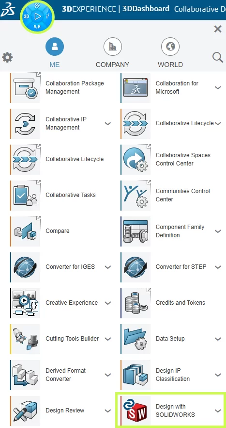
            • Navigate to the Compass (top-left menu)
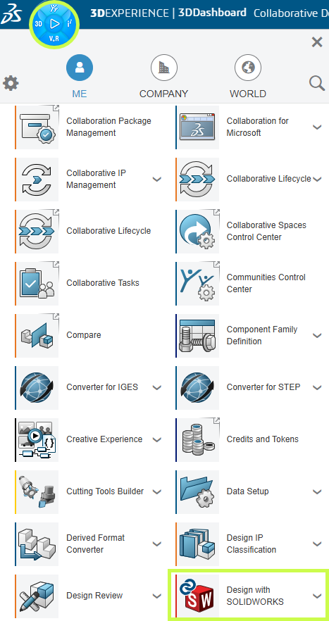
            • Scroll down to My Apps and locate Design with SOLIDWORKS.
            • Select the app to begin the installation.
            • Click Install Launcher when prompted
            • Run the installer

            This tool acts as the bridge between your browser and desktop applications.

            Step 5: Install “Design with SOLIDWORKS”

            This is the most important step.

            The Design with SOLIDWORKS connector is what links your desktop SOLIDWORKS environment to the platform, and enables AI-driven features.

            Installation Steps:

            • In the platform, search for Design with SOLIDWORKS
            • Click Install
            • Accept default settings (recommended)
            • Complete installation
            • Restart your machine if prompted

            Once installed, your environment is officially “connected.”

            Having trouble? Check out our installation guide:
            Connect SOLIDWORKS Desktop to the 3DEXPERIENCE Platform

            Step 6: Launch SOLIDWORKS from the Platform

            This step is often missed, however, it is absolutely critical.

            First Launch:

            • Go to the platform
            • Click Open on Design with SOLIDWORKS
            • Launch SOLIDWORKS from the browser

            Why this matters:

            This ensures:

            • Your session is authenticated
            • The connector is active
            • Cloud services are initialized

            If you launch SOLIDWORKS directly from your desktop first, you may not be connected properly.

            Step 7: Verify the 3DEXPERIENCE Add-in

            Once SOLIDWORKS opens, confirm everything is working.

            Check:

            • A 3DEXPERIENCE tab appears in the task pane
            • Add-in is enabled under:
              Tools > Add-ins

            If it’s not active:

            • Enable it manually
            • Restart SOLIDWORKS if needed

            This confirms your system is fully connected.

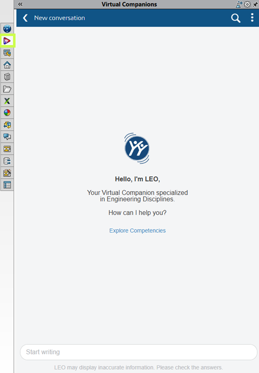
            Step 8: Access the Virtual Companions Tab

            Now we get to the interesting part.

            With everything configured, you should have access to Virtual Companions, where new AI-driven tools are introduced.

            Where to Find It:

            • Inside SOLIDWORKS (Task Pane)
            • Look for Virtual Companions tab

            Virtual Companions Tab

            What You’ll Find:

            • Experimental AI features
            • Early access tools
            • Workflow enhancements powered by AI

            These features evolve quickly, so expect changes over time.

            Step 9: Start Using AI Features (Practical Examples)

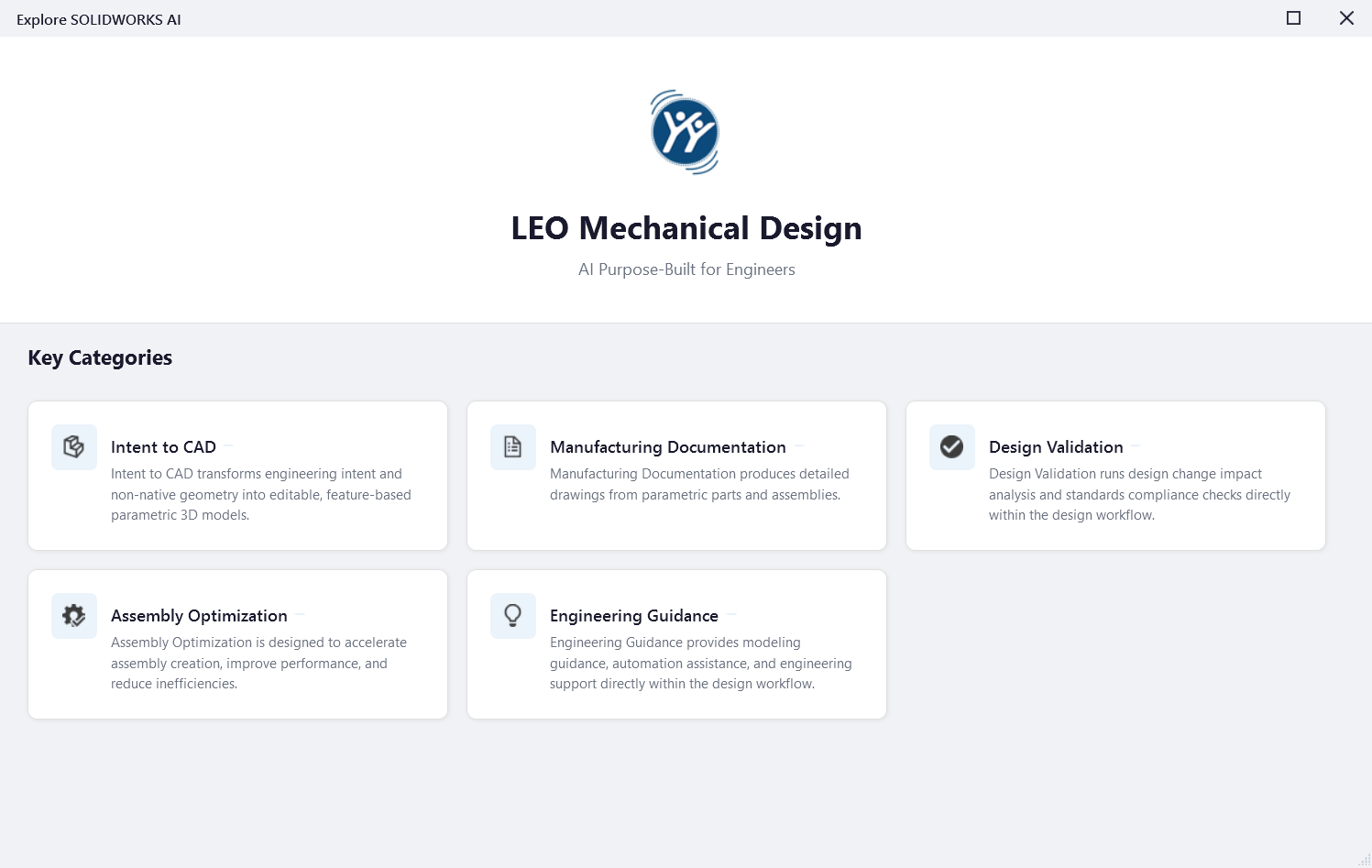
            Once inside Virtual Companions, click the potion icon the top right to explore SOLIDWORKS AI competencies:

            Virtual Companions

            Good First Use Cases:

            Click the different categories for examples of prompts you can use to get started.

            AI Companion First Case

            Step 10: Best Practices for Getting Started

            This is where most teams succeed or struggle.

            ✔ Start Small

            Don’t try to overhaul your entire workflow.

            ✔ Focus on Real Problems

            Look for:

            • Repetitive tasks
            • Bottlenecks
            • Manual processes

            ✔ Validate Everything

            AI suggestions still require engineering judgment.

            ✔ Train Your Team Gradually

            Adoption works best when it’s incremental.

            Final Thoughts: Where AI in SOLIDWORKS Is Headed

            AI in SOLIDWORKS is evolving, but the direction is clear:

            • More automation of low-value tasks
            • Better decision support
            • Deeper integration with simulation and data

            And importantly:

            SOLIDWORKS isn’t being replaced, it’s being enhanced.

            For most teams, the real opportunity isn’t jumping ahead, it’s simply getting started.

            For more information on AI in SOLIDWORKS, reach out to us through our website:
            SOLIDWORKS AI: Transform Your Design with Artificial Intelligence


            Michael Habrich

            3DEXPERIENCE Specialist

            X_green_halo

            Any questions? Need help? Ask one of our experts.

            Whether you’re ready to get started or just have a few more questions, you can contact us toll-free:
              AI won’t replace you. Someone using AI will.

              BLOG

              AI won’t replace you. Someone using AI will.

              [techtips_featured_image_shortcode]

              AI may not be perfect yet, but it’s precisely why you should start using it today.

              We’ve grown used to talking about artificial intelligence as if the story began in 2022. ChatGPT arrives, the public adopts it, and suddenly AI becomes a topic of casual conversation. But if we want to properly understand what’s happening, we must not confuse media frenzy with historical reality. OpenAI did release ChatGPT publicly (“research preview”) on November 30, 2022, and yes, it was a real social inflection point.

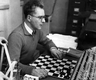
              But AI as a field is much older. Turing formalized the intellectual framework of the “imitation game” as early as 1950, and the Dartmouth Proposal (1955) explicitly announced a summer 1956 project dedicated to “artificial intelligence.” Some early demonstrations also appeared quickly: the Ferranti Mark I ran a limited chess program in 1951 (mate-in-two).

              This reminder is not meant to give you a history lesson. It serves one purpose: AI is not a feature. It is a trajectory.

              And it resembles another well-known human trajectory: that of fire.

              The Fire Analogy: Understanding a Technology We Don’t Yet Understand

              At this point, you’re probably thinking: “What is he talking about?” Stay with me.

              One day, in a cave, one of our ancestors discovered fire. At first, this discovery served very specific purposes: heating, lighting, protection. These were not “industrial innovations”; they were immediate uses. And yet, the full chain – metallurgy, machines, steel industries – that followed from this same discovery reshaped modern history. The human on day one could not imagine the human of today. Not because they were less intelligent, but because they lacked perspective.

              We are at the same stage. Except instead of holding a torch, we are writing prompts. And the typical mistake in 2026 is judging AI based on what it is today, as if it were representative of tomorrow’s trajectory.

              The Real Signal: Speed of Evolution

              What matters is not only what AI does today. What matters is how fast it improves. To make that speed tangible, a cultural artifact has emerged: the “Will Smith Eating Spaghetti test,” now documented as an informal benchmark.

              Case Study: The “Spaghetti Test”

              In its 2023 version, human motion is unstable: faces and hands deform, physics is not believable. In the 2026 version, the result becomes coherent enough that the difference is obvious: we are no longer looking at a “grotesque meme,” but at a rendering that requires a critical eye to detect AI involvement.

              What matters here is the underlying learning dynamic. The progression observed between 2023 and 2026 cannot be attributed solely to model improvements. It is also the result of user adoption.

              Early uses produced low-quality, unstable, and difficult-to-use outputs. However, these experiments helped gradually identify model limitations, refine interaction methods (prompts, iterations, post-processing), and structure more robust practices.

              In other words, the improvement in outputs in 2026 is inseparable from the learning accumulated by users over time. Current performance is not only technological; it is also cognitive and methodological.

              This is how the concept of cumulative advantage should be understood: it does not rely solely on access to technology, but on the experience gained by using it under imperfect conditions.

              From Internet Culture to the Engineering Office: Why SOLIDWORKS Is Concerned

              The transition from “spaghetti → SOLIDWORKS” is not arbitrary. It is the same mechanism applied in a different context. A general-purpose technology crosses a threshold, then infiltrates products, becomes invisible, and ultimately reshapes practices.

              We’ve already seen this in the 2010s: AI did not “look like ChatGPT,” but it was already embedded in everyday life. Google Maps, for example, deployed models (including graph neural networks) at scale for ETA (Estimate Time of Arrival) and traffic prediction. The result: you use AI without thinking about it. The advantage rarely comes from an “AI button,” but from the routines that evolve around your activity.

              SOLIDWORKS 2026: The AI Shift Is Underway

              This is exactly the same dynamic in SOLIDWORKS.

              SOLIDWORKS 2026 already integrates AI into areas where real time is lost: drawings, assemblies, and access to knowledge. Dassault Systèmes presents SOLIDWORKS 2026 as an “AI-powered” portfolio (design, collaboration, data management).

              A clear example: Auto-Generate Drawings (BETA). The “What’s New in SOLIDWORKS 2026” documentation explicitly describes automatic drawing generation, including section views and hole callouts.

              The same logic applies to assemblies: SOLIDWORKS documents AI-based fastener recognition to automatically create SmartMates, with explicitly listed limitations. This level of detail is precisely what makes the promise credible (and reminds us that this is not “magic,” but engineering with constraints).

              Rather than listing every available feature, it is more relevant to focus on the direction: Dassault introduces “Virtual Companions” (AURA, LEO, MARIE), with AURA and LEO already available and MARIE announced soon. SOLIDWORKS also highlights “AI-guided” features in FD01 (guided analysis, guided creation).

              What matters here is not proving that everything is ready. It is recognizing that AI has entered the tool, meaning the learning process has begun, whether you like it or not. And it is moving fast.

              Waiting for Maturity: A Strategic Mistake

              Let’s be clear: in 2026, all of this is still imperfect. And that is normal. We are at the “spaghetti 2023” stage of AI-assisted CAD: promising, functional in certain areas, but not yet obvious everywhere.

              The instinctive reaction for many teams is: “we’ll wait until it’s mature.”

              This reaction is human. But strategically, it is a serious mistake.

              In 2025, we clearly entered a phase of mass adoption. Nearly 88% of organizations report using AI in at least one function, compared to 78% the previous year. This adoption is accelerating and follows an exponential curve.

              From an economic perspective, the signals are just as clear. The generative AI market reached nearly $60 billion in 2025 and could exceed $400 billion by 2031.

              In industry, the shift is already visible: nearly 76% of manufacturing companies are using AI in 2026.

              But the most interesting point is not adoption. It is the gap between adoption and impact. Despite massive investments, only about 5% of companies currently manage to generate significant value from AI. In most cases, projects remain stuck at the experimental stage, and the majority of initiatives never reach production.

              In other words: everyone has access to AI, but very few truly know how to use it. So “waiting” does not mean being cautious. It means allowing a capability gap to form. Because knowing how to use AI is a skill. And it must be learned.

              What Research Says About Gains (and Their Limits)

              To address the assumption “we’ll wait until AI is ready,” it is important to understand a key nuance: AI does not deliver uniform gains, and that is precisely why early learning matters.

              The operational conclusion is simple: early adoption is not a blind bet; it is a mapping phase. It helps you understand when AI works, when it fails, and most importantly how to control it.

              What It Really Changes: Redefining Engineering Performance

              This is where the thesis becomes concrete: AI will not replace you. A competitor who masters it will.

              And I mean mastery in the strict sense. Asking ChatGPT for a carbonara recipe does not count. We are talking about work practices, standards, quality control, understanding when AI accelerates a task and when it introduces risk, knowing where to integrate AI in a project without breaking traceability, and knowing how to train teams without creating blind dependency.

              In other words, mastery is not built when the tool becomes “perfect.” It is built while it is imperfect, because that is when you establish your standards, your checklists, your controls, and your best practices.

              Ultimately, the value of an engineer will not only be their technical skill. It will be their ability to amplify that skill with properly framed AI.

              Conclusion: From Intention to Action

              The question is no longer whether you are using AI. It is already present in your tools, your processes, and your competitive environment.

              The real question is whether you are learning to use it properly.

              Like all major technological transformations, the advantage does not go to those who wait for everything to stabilize. It goes to those who start while it is still imperfect, who experiment, who structure, and who gradually build solid methods.

              AI does not replace engineering. It redefines its standards.

              And this transition does not happen alone.

              At solidxperts, our teams are already working with these tools on a daily basis. We support companies in implementing practical AI use cases in SOLIDWORKS: identifying relevant use cases, integrating them into existing processes, training teams, and establishing reliable standards.

              If you want to understand concretely what AI can bring to your environment, we offer demos and working sessions tailored to your reality.

              The simplest next step is to start the conversation.


              Max Laramée

              Max Laramée

              Marketing Director

              X_green_halo

              Any questions? Need help? Ask one of our experts.

              Whether you’re ready to get started or just have a few more questions, you can contact us toll-free:
                Connecting SOLIDWORKS Desktop to the 3DEXPERIENCE Platform

                BLOG

                Connecting SOLIDWORKS Desktop to the 3DEXPERIENCE Platform

                [techtips_featured_image_shortcode]

                The 3DEXPERIENCE platform includes a wide range of powerful, web-based apps, but many teams prefer to continue designing in the familiar SOLIDWORKS desktop environment. The good news? You don’t have to choose one or the other.

                By combining SOLIDWORKS desktop with the Design with SOLIDWORKS connector, you can keep your existing workflows and interface while taking full advantage of cloud-based file storage, sharing, and collaboration.

                In this article, we’ll walk through:

                • Installing the Design with SOLIDWORKS connector

                • Launching SOLIDWORKS with the 3DEXPERIENCE connection enabled

                • Saving files directly to the platform

                • Managing your local cache for best performance

                Installing Design with SOLIDWORKS

                First, once your 3DEXPERIENCE tenant is activated, or you’ve been invited to an existing one , linking SOLIDWORKS desktop to the platform is quick and straightforward.

                • In the 3DEXPERIENCE interface, click the Compass icon in the upper-left corner.

                • Scroll down to My Apps and locate Design with SOLIDWORKS.

                • Select the app to begin the installation.

                Installing Design with SOLIDWORKS

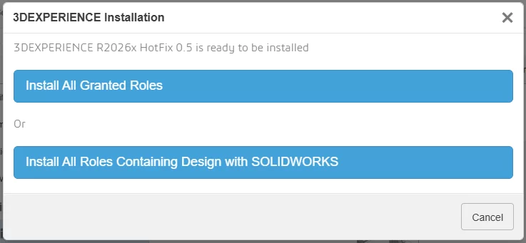
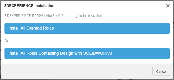
                During installation, you’ll be prompted to:

                • Install all granted roles, or

                • Install only the roles required for the Design with SOLIDWORKS connector

                Installing Design with SOLIDWORKS

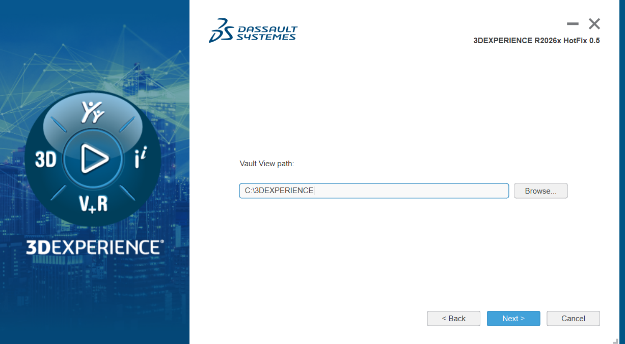
                The installer will then allow you to choose:

                • The installation directory

                • The location of your 3DEXPERIENCE cache

                By default, the cache is stored in C:\3DEXPERIENCE. Since the cache is managed directly from within SOLIDWORKS, you typically won’t need to access this folder manually.

                The cache is stored in C:\3DEXPERIENCE

                Once installation is complete, the connector is added to your system.

                Enabling the 3DEXPERIENCE Add-In in SOLIDWORKS

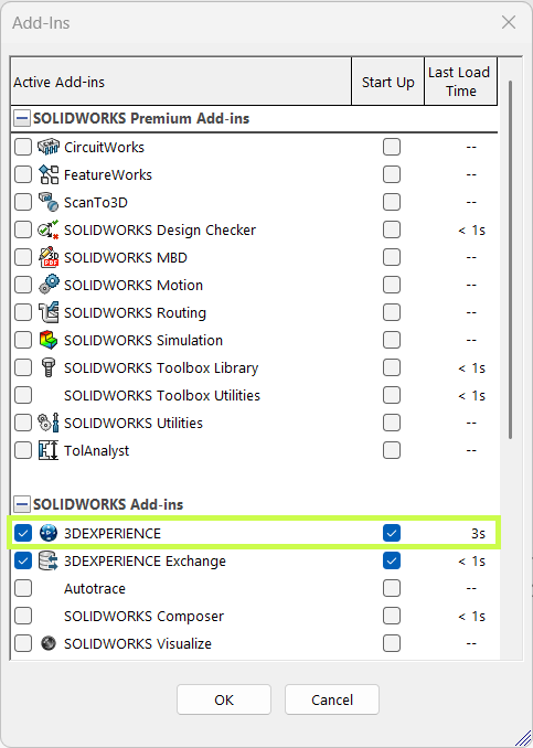
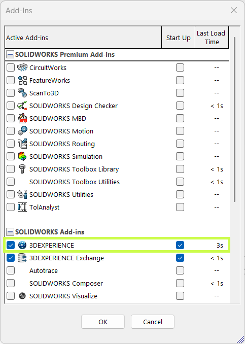
                Before using the connector, take a moment to confirm the 3DEXPERIENCE add-in is enabled in SOLIDWORKS.

                • Launch SOLIDWORKS.

                • Go to Settings > Add-Ins.

                • Verify that the 3DEXPERIENCE add-in is installed and checked.

                Enabling the 3DEXPERIENCE Add-In in SOLIDWORKS

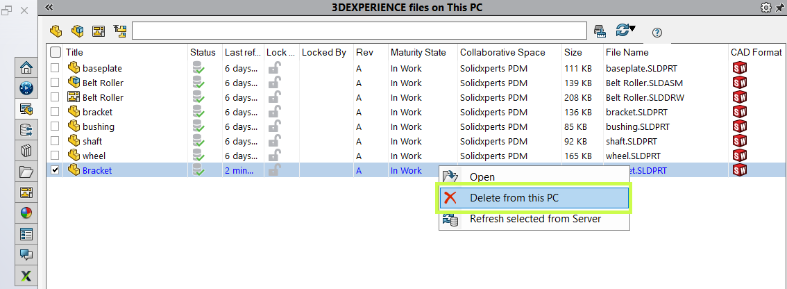
                This ensures SOLIDWORKS can communicate properly with the platform.

                Launching SOLIDWORKS with the Connector

                One important workflow change to be aware of is how you launch SOLIDWORKS.

                • Launching SOLIDWORKS from a desktop shortcut or system search opens the standard desktop version without the 3DEXPERIENCE connection.

                • To use the connector, launch Design with SOLIDWORKS instead.

                This starts SOLIDWORKS with full 3DEXPERIENCE functionality enabled.

                You can also:

                • Use the dropdown next to Design with SOLIDWORKS to check for updates or uninstall

                • Create a dedicated desktop shortcut for Design with SOLIDWORKS, allowing you to access cloud functionality without opening a web browser

                Launching SOLIDWORKS with the Connector

                Saving Files to the 3DEXPERIENCE Platform

                Once connected, saving files to the cloud is seamless.

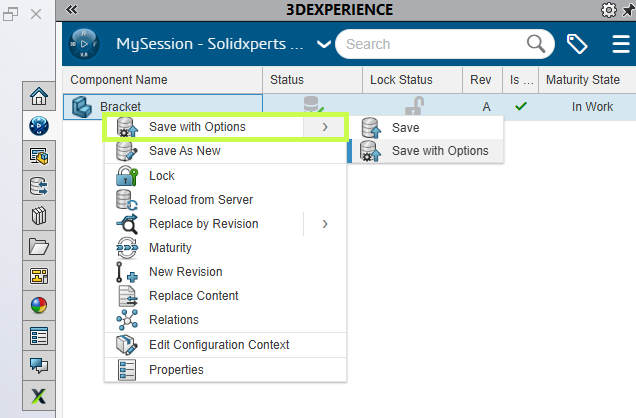
                You can:

                • Use Save to 3DEXPERIENCE from the File menu (alongside Save and Save As), or

                • Use the 3DEXPERIENCE Task Pane, added by the add-in

                The task pane lets you:

                • Browse your tenant

                • Search for existing data

                • Right-click and save files directly to the platform

                And if needed, you can still save files locally, the connector doesn’t force you into a cloud-only workflow.

                Saving Files to the 3DEXPERIENCE Platform

                Managing the 3DEXPERIENCE Cache

                When you open or edit files stored on the platform, they’re downloaded locally to your 3DEXPERIENCE cache. Keeping this cache clean can significantly improve performance.

                The 3DEXPERIENCE add-in makes cache management easy:

                • Delete individual cached files

                • Use the cleanup tool to remove files older than a specified date

                The cleanup utility is smart. It automatically skips:

                • Files referenced by assemblies

                • Files not yet saved to the platform

                • Files that are currently locked

                This helps you clear space without risking your data.

                Saving Files to the 3DEXPERIENCE Platform

                Final Thoughts

                The Design with SOLIDWORKS connector bridges the gap between SOLIDWORKS desktop and the 3DEXPERIENCE platform, giving you the best of both worlds. You get cloud-based collaboration and data management without changing how you design.

                If you need help installing the connector, optimizing your workflow, or rolling this out to your team, your Solidxperts team is here to help.

                Looking to learn more?

                • Explore additional articles and tutorials

                • Connect with other users and experts

                • Or reach out to us! We’re always happy to help you get the most out of your tools


                Michael Habrich

                3DEXPERIENCE Specialist

                X_green_halo

                Any questions? Need help? Ask one of our experts.

                Whether you’re ready to get started or just have a few more questions, you can contact us toll-free:
                  7 Myths About AI: Demystifying Bias and Technological Limits

                  BLOG

                  7 Myths About AI: Demystifying Bias and Technological Limits

                  [techtips_featured_image_shortcode]

                  Every wave of innovation in artificial intelligence (AI) brings real technological progress, along with a dramatic rise in hype. With every breakthrough, new narratives emerge: AI is portrayed as “magical,” endowed with its own will, on the verge of becoming superhuman, or conversely as something completely uncontrollable by law.

                  As a result, this fog of myths makes AI opaque to the public, complicates decision-making for organizations, and distracts attention from the real technical and societal challenges.

                  In this article, we aim to clarify two key questions:

                  • What are the main myths currently surrounding AI?

                  • And what technical, physical, and social realities help dismantle them?

                  The Major Myths Shaping Our View of AI

                  Several myths structure today’s collective imagination about artificial intelligence.

                  “AI has agency.”
                  The idea that AI systems act on their own initiative, with intentions, goals, or desires.

                  “Superintelligence is imminent.”
                  The belief that we are only a few years, or even months, away from a general intelligence far surpassing human capabilities.

                  “AI can be objective or impartial.”
                  The assumption that algorithms are inherently neutral because they rely on computation.

                  “AI has a clear definition.”
                  As if AI referred to a single, clearly defined technology, when in reality no universal definition exists.

                  “Ethical guidelines are enough to protect us.”
                  The perception that voluntary ethical charters are sufficient safeguards against harmful AI uses.

                  “AI cannot be regulated.”
                  The claim that technological innovation moves too fast for legal systems to keep up.

                  “AI can solve any problem.”
                  The idea that AI is a universal solution applicable to any technical, economic, or social challenge.

                  In reality, these myths stem from a mixture of marketing, science fiction, and technical misunderstanding. To move beyond them, we need to return to what AI actually is today.

                  1. Agency and Consciousness: AI as a “Stochastic Parrot”

                  One of the most common misconceptions is attributing intention to AI. We often talk about what AI “wants,” “decides,” or “thinks.” Yet modern systems, especially large language models (LLMs), function much more simply.

                  Models That Predict, Not Understand

                  An LLM does not interpret your sentences in the human sense. Technically, it:

                  • receives a sequence of tokens (pieces of words) as input

                  • computes a probability distribution over the next token using a trained neural network

                  • selects or samples the next token according to this distribution

                  • repeats the process until a complete response is produced

                  This mechanism relies on massive statistical correlations learned during training. At no point does the system possess:

                  • semantic understanding of concepts

                  • an internal model of the world comparable to a human’s

                  • independent intentions or goals

                  In other words, what researchers sometimes call a “stochastic parrot”: a machine that reproduces learned language structures in sophisticated probabilistic combinations.

                  Anthropomorphism as a Persistent Bias

                  If these systems appear to “think,” it is largely because humans naturally anthropomorphize systems that display seemingly intelligent behavior. This cognitive bias is central to many misunderstandings about AI today.

                  2. Superintelligence and the Resource Wall

                  Another dominant narrative suggests that we are on the verge of general superintelligence, held back only by corporate caution. However, the actual infrastructure behind AI tells a different story.

                  The Data Wall: A Finite Resource

                  Today’s large models rely on enormous volumes of high-quality human-generated data: text, conversations, code, and multimedia content. But this resource is not infinite.

                  Estimates suggest that high-quality training data suitable for ever-larger models could be largely exhausted between 2026 and 2032. Beyond that point:

                  • existing datasets would be reused repeatedly, yielding limited improvements

                  • or synthetic data would be used, introducing new risks and feedback loops

                  Physical Constraints and Diminishing Returns

                  The idea of unlimited growth in model power faces several practical limits.

                  Energy and cooling constraints
                  The computing density required for training and deploying the largest models pushes data centers toward limits in:

                  • electrical grid capacity

                  • cooling infrastructure needed to dissipate heat

                  Hardware limits
                  GPUs and other accelerators are approaching physical limits in terms of performance per watt and cost efficiency.

                  Diminishing returns
                  Scaling models by increasing parameters, data, or compute still improves performance, but each additional gain becomes smaller relative to the resources invested.

                  These “resource walls” do not prevent progress, but they challenge the idea of a straightforward path toward limitless superintelligence.

                  3. Objectivity and Impartiality: AI as a Mirror of Human Bias

                  AI is often presented as a way to eliminate human bias. In reality, AI systems frequently inherit and sometimes amplify existing inequalities.

                  Data Bias: Who Is Represented?

                  Models can only generalize effectively if training data represent a sufficiently diverse set of situations and populations.

                  When datasets are imbalanced, performance degrades unevenly. Studies have shown, for instance, that some facial recognition systems exhibit error rates up to 35% higher for darker-skinned women than for white men.

                  This is not an isolated bug. It reflects underlying representation biases in the data.

                  Design Bias: Optimization Choices Matter

                  Even with balanced datasets, models reflect the priorities of their designers:

                  • How is overall accuracy balanced against fairness between groups?

                  • Which metrics are optimized during training and deployment?

                  • What trade-offs are accepted between false positives and false negatives?

                  These decisions directly shape who benefits from an AI system and who may be harmed. Claims of algorithmic objectivity often overlook these design choices.

                  4. The Plural Architecture of AI

                  Contrary to popular belief, “artificial intelligence” does not describe a single unified technology. Instead, it is an umbrella term covering a broad and heterogeneous set of methods, theories, and applications.

                  A Hierarchy of Often-Confused Concepts

                  Many people use AI, Machine Learning, and Deep Learning interchangeably, although they represent different levels of abstraction.

                  Artificial Intelligence (AI)
                  The broader field of computer science focused on creating systems capable of performing tasks that require human-like cognitive abilities.

                  Machine Learning (ML)
                  A subset of AI in which systems learn patterns from data rather than relying solely on explicit programming.

                  Deep Learning (DL)
                  A specialized ML approach using multi-layer neural networks to process complex data such as images, speech, or language.

                  Divergent Definitions

                  The meaning of AI changes depending on perspective.

                  • Scientific definition: a research discipline exploring computational models of cognition.

                  • Technological definition: systems capable of perceiving their environment and taking actions accordingly.

                  • Popular definition: a largely anthropomorphic vision attributing awareness or autonomy to machines.

                  A Fragmented Ecosystem

                  AI is not monolithic. It includes multiple research traditions and technical approaches.

                  Two historical families illustrate this diversity:

                  Symbolic AI
                  Systems based on logical rules and expert knowledge.

                  Connectionist AI
                  Statistical approaches based on large datasets and neural networks, including modern language models.

                  Narrow AI vs General AI

                  Today’s systems belong entirely to narrow AI, designed to perform specific tasks such as:

                  • playing chess

                  • recognizing objects in images

                  • detecting fraud

                  • generating text

                  Artificial General Intelligence (AGI), capable of learning any intellectual task a human can perform, remains a speculative concept.

                  5. Ethics, Marketing, and the Need for Regulation

                  In response to AI risks, many organizations have adopted ethical charters and voluntary guidelines. While useful, these tools have clear limitations.

                  Ethical Marketing

                  Without enforcement mechanisms, many ethical charters function more as reputation tools:

                  • they reassure stakeholders

                  • they improve brand image

                  • but they rarely prevent high-risk systems from being deployed

                  Toward Enforceable Regulation: The EU AI Act

                  Contrary to the myth that AI cannot be governed, regulatory frameworks are emerging.

                  The European Union’s AI Act proposes a risk-based approach:

                  • Unacceptable risk systems are banned

                  • High-risk systems must comply with strict requirements including transparency, traceability, documentation, conformity assessments, and human oversight

                  • Minimal risk systems face limited regulation

                  The goal is not to slow innovation, but to ensure that AI systems remain accountable within existing legal frameworks.

                  6. AI Is Not a Magic Wand

                  Perhaps the most persistent myth is that AI can solve any problem.

                  In reality, successful AI systems are:

                  • specialized, designed for specific tasks such as image recognition, text summarization, fraud detection, or code generation

                  • limited in common sense, often failing when faced with situations outside their training distribution

                  • highly context-dependent, relying on data quality, system integration, and human oversight

                  The same model may perform extremely well in a well-defined environment yet fail dramatically when conditions change or when real-world usage diverges from intended scenarios.

                  AI as a Component, Not a Strategy

                  For organizations, AI should be viewed as:

                  • a technical component within a larger system architecture

                  • integrated into a broader strategy involving governance, metrics, risk management, and human supervision

                  The wrong question is:

                  “How can we add AI everywhere?”

                  The better question is:

                  “On which well-defined problems does AI provide a real advantage compared to existing solutions?”

                  Moving Beyond the Myths

                  Today’s AI is neither a conscious entity, nor an imminent superintelligence, nor a universal solution.

                  It is a set of powerful techniques deeply grounded in real-world constraints. These systems are limited by physical infrastructure such as energy, cooling, and hardware, as well as by the availability of data and computational resources. They are also shaped by the social structures and human biases embedded in the data and objectives guiding their development.

                  By dismantling the myths surrounding AI, autonomous agency, imminent superintelligence, perfect objectivity, legal ungovernability, or universal applicability, we can ask better technical questions, design safer systems, and build more effective regulatory frameworks.

                  Ultimately, understanding these realities allows us to treat AI for what it truly is: a powerful but specialized tool that must be used with rigor, transparency, and human oversight.

                  If you have questions about AI and its practical applications, our experts are here to help. Contact us to start the conversation.


                  Benoit Bilodeau

                  Senior Solutions Architect

                  X_green_halo

                  Any questions? Need help? Ask one of our experts.

                  Whether you’re ready to get started or just have a few more questions, you can contact us toll-free:
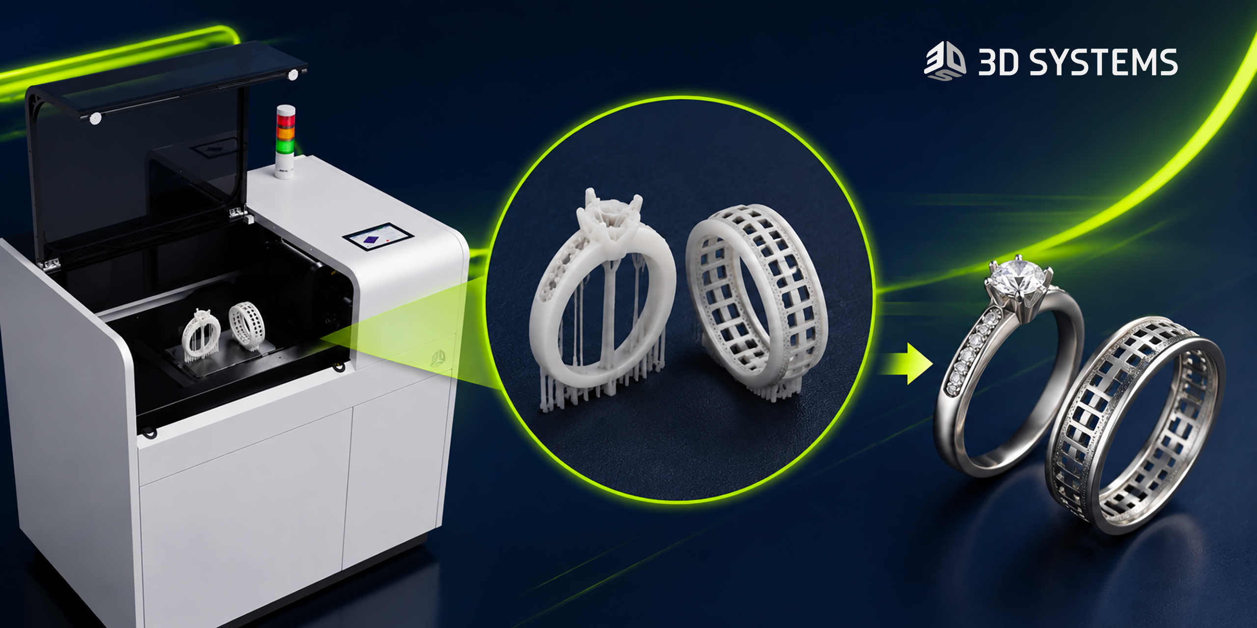
                    Artificial Intelligence in Engineering: Automation Without Losing the Human Touch

                    BLOG

                    Artificial Intelligence in Engineering: Automation Without Losing the Human Touch

                    [techtips_featured_image_shortcode]

                    Artificial intelligence (AI) is playing an increasingly important role in engineering processes, particularly when it comes to automating repetitive tasks and accelerating the production of technical documentation. However, its role remains fundamentally complementary to that of engineers. Creativity, domain expertise, and decision-making responsibility remain human.

                    In this article, we explore:

                    • what AI concretely brings to engineering

                    • which tasks remain (and will remain) human

                    • how to organize an effective human–machine collaboration

                    • and what this means for the engineering profession

                    1. What AI concretely brings to engineering

                    1.1 Automating repetitive, low-value tasks

                    The daily work of engineering teams is filled with essential but repetitive tasks that consume a great deal of time without fully leveraging engineers’ expertise. This is precisely where AI excels.

                    A typical example is generating technical drawings from 3D models.

                    Traditionally, producing technical drawings involves:

                    • manually creating the different views (front, section, detail views)

                    • applying dimensioning and tolerancing standards

                    • reusing elements from previous projects, often manually

                    • performing successive checks for consistency and compliance

                    With AI, a large portion of this work can be:

                    • automated: generating technical drawings directly from 3D designs

                    • contextualized: taking into account company history, internal standards, and previously validated models

                    The result: fewer repetitive clicks and more time for analysis and improvement.

                    1.2 Measurable efficiency gains

                    The operational impact is far from marginal.

                    Where dozens of people were previously needed to produce, adjust, and verify detailed drawings, organizations can now concentrate human work within a smaller team of reviewers responsible for:

                    • correcting the remaining inconsistencies

                    • validating compliance

                    • managing special cases not covered by the models

                    AI handles the repetitive heavy lifting. Humans focus on quality, reliability, and exception management.

                    2. Tasks that remain (and will remain) human

                    Despite these gains, certain activities remain difficult to automate and may remain so in the short and medium term.

                    2.1 Creative design and early project phases

                    The early stages of a project, when the architecture of a product and the major technical choices are defined, rely on:

                    • creativity

                    • accumulated domain expertise

                    • the ability to integrate sometimes ambiguous constraints (real-world usage, environment, maintenance, ergonomics)

                    • complex decision-making that affects overall product performance

                    These activities require systemic understanding, multi-criteria trade-offs, and a form of intuition that current AI models cannot replicate.

                    2.2 Safety, compliance, and responsibility

                    A clear example is the design of powerful machinery.

                    Engineers must:

                    • integrate safety factors to protect users

                    • sometimes introduce additional margins based on experience or real-world conditions that are difficult to simulate

                    These decisions directly affect safety, regulatory compliance, and legal responsibility.

                    Today, these types of decisions cannot be delegated to AI.
                    Decision-making responsibility remains with humans, not algorithms.

                    3. Toward intelligent human–machine collaboration

                    The key question is therefore not whether AI will replace engineers, but how to organize an effective collaboration between the two.

                    3.1 AI as a copilot during design

                    During the design process, AI can act as a copilot or technical assistant. For example, it can:

                    • propose lighter materials that still meet strength requirements

                    • suggest geometric variations to reduce weight or improve rigidity

                    • quickly analyze the impact of small design changes on overall performance

                    In practice, engineers can ask AI questions such as:

                    • “Which materials meet these strength and weight constraints?”

                    • “What geometric alternatives could reduce the mass by 10 percent?”

                    However, final validation, trade-off decisions, and system integration remain the responsibility of the engineer.

                    3.2 AI as an analyst for standardized tasks

                    For more standardized analytical tasks, AI becomes a particularly useful engineering assistant. It can support:

                    • the processing and structuring of large volumes of data

                    • the automatic generation of variants for comparative studies

                    • consistency checks across large sets of technical documentation

                    This allows teams to explore more possibilities in less time, without removing the engineer from the decision-making process.

                    4. Should engineers fear being replaced by AI?

                    The fear of being replaced by machines is real and understandable, especially in technical professions.

                    4.1 Vulnerable jobs vs resilient jobs

                    A job is more exposed to automation when its tasks are:

                    • repetitive

                    • highly standardized

                    • not very creative

                    • associated with limited decision-making

                    In contrast, a job is more resilient when it involves:

                    • significant creativity

                    • a global understanding of complex systems

                    • multi-criteria trade-offs (cost, performance, risk, environmental impact)

                    • strong responsibility for safety, compliance, or performance

                    In engineering, activities such as:

                    • defining a product’s overall architecture

                    • breakthrough innovation

                    • high-impact technical decisions

                    • field responsibility

                    remain firmly within the human domain.

                    4.2 A change in role rather than disappearance

                    Consider the example of technical documentation.

                    Yes, AI can generate documents based on validated models or historical data.

                    No, it does not replace engineers when it comes to:

                    • critical decision-making

                    • technical trade-offs

                    • creative innovation

                    What changes most is how time is allocated:

                    • less manual and repetitive production work

                    • more design, analysis, validation, and innovation

                    Toward augmented engineering, not automated engineering

                    Artificial intelligence brings real value to engineering by:

                    • automating repetitive, low-value tasks

                    • accelerating the generation of drawings and technical documentation

                    • assisting engineers in exploring design alternatives and performing analysis

                    However, creativity, domain expertise, and responsibility remain central to the engineer’s role.

                    The goal is not to replace humans, but to build intelligent collaboration:

                    • letting AI handle what it does best (speed, repetition, scale)

                    • preserving what defines engineering expertise: inventing, evaluating trade-offs, and taking responsibility for decisions

                    The future of engineering will not be “human or AI,” but clearly human + AI: augmented engineering that is more efficient, safer, and more focused on innovation.


                    Benoit Bilodeau

                    Senior Solutions Architect

                    X_green_halo

                    Any questions? Need help? Ask one of our experts.

                    Whether you’re ready to get started or just have a few more questions, you can contact us toll-free:
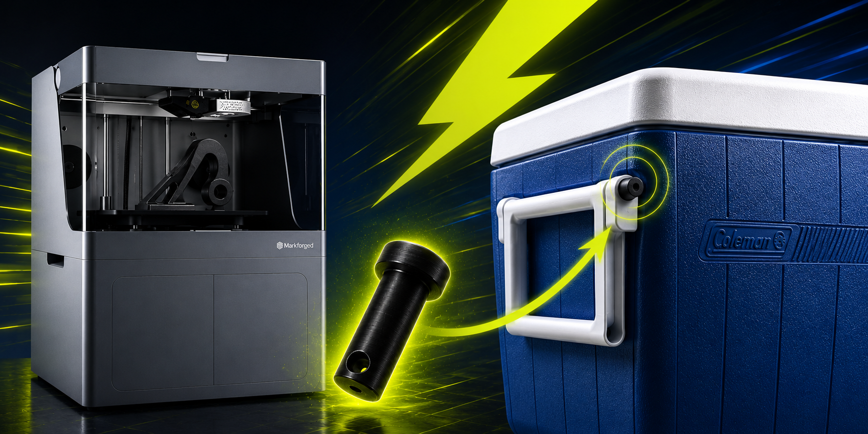
                        Download

                          Download

                            Download