SolidXperts Celebrates 25 Years of Design and Innovation!

BLOG

SolidXperts Celebrates 25 Years of Design and Innovation!

[techtips_featured_image_shortcode]

It’s been 25 years since SolidXperts first started its adventure as an engineering and technology services provider. Over the years, the company has grown to become Quebec’s leader in SOLIDWORKS 3D design, automation, and 3D printing services. To celebrate this milestone we wanted to take a look back at our company’s journey, to see how it has evolved over the years. We’ve come a long way and we couldn’t be prouder of what we’ve achieved together. 


SolidXperts was founded in February of 1998, when now CEO Alex Habrich received a CD in the mail from a local SOLIDWORKS VAR, asking him to consider using SOLIDWORKS for his engineering projects. Impressed by the product’s functionality and affordable price, he immediately picked up the phone and spoke to SOLIDWORKS in Boston and asked to come down to speak in person. 


In that meeting, it was announced to Alex that Dassault had just made an offer to acquire SOLIDWORKS, and though they hadn’t closed yet, they were in the midst of finalizing the paperwork. With a signature and a handshake, SolidXperts debuted into the 3D design and manufacturing world as an official SOLIDWORKS reseller. 


We focused on providing best-in-class CAD software to small and medium enterprises. We quickly realized that our expertise could help companies of all sizes, so we expanded our services to become a one-stop shop for all 3D product design needs, including CAD, training, coaching, project consulting, PDM and PLM services, a full range of 3D printers, and much more. We provide expertise in a wide range of areas, including software development, system integration, and industrial automation. 


Our services have grown and adapted to meet the needs of our customers, and today we offer a comprehensive suite of engineering and technology services. We are proud to be a leader in the engineering and technology services industry, and we are constantly striving to improve our services and products. 


As things have progressed over the decades, Dassault in its efforts in commercialization is now looking to bring a lot of the technologies together. So, it just makes natural sense for the SolidXperts and its sister-company Mecanica to work under one umbrella, The SolidXperience Group. Today, SolidXperts is one of the most trusted and reliable providers of 3D design and product manufacturing solutions in Canada and the U.S. 


At SolidXperts, we are committed to delivering quality and reliable services to our customers. We have a team of experienced engineers and technology professionals who are always ready to help our customers achieve their goals. We are proud to be celebrating our 25th anniversary, and we want to thank our customers for their continued support. Over the years, we have worked with a wide range of customers, from small businesses to large corporations and government organizations. We couldn’t have achieved our success without their trust and partnership! 

X_green_halo

Any questions? Need help? Ask one of our experts.

Whether you’re ready to get started or just have a few more questions, you can contact us toll-free:

    What’s new in SOLIDWORKS PDM 2023: Data Cards Tooltips

    BLOG

    What’s new in SOLIDWORKS PDM 2023: Data Cards Tooltips

    By: Benoit Bilodeau, Director – Product Data Management

    [techtips_featured_image_shortcode]

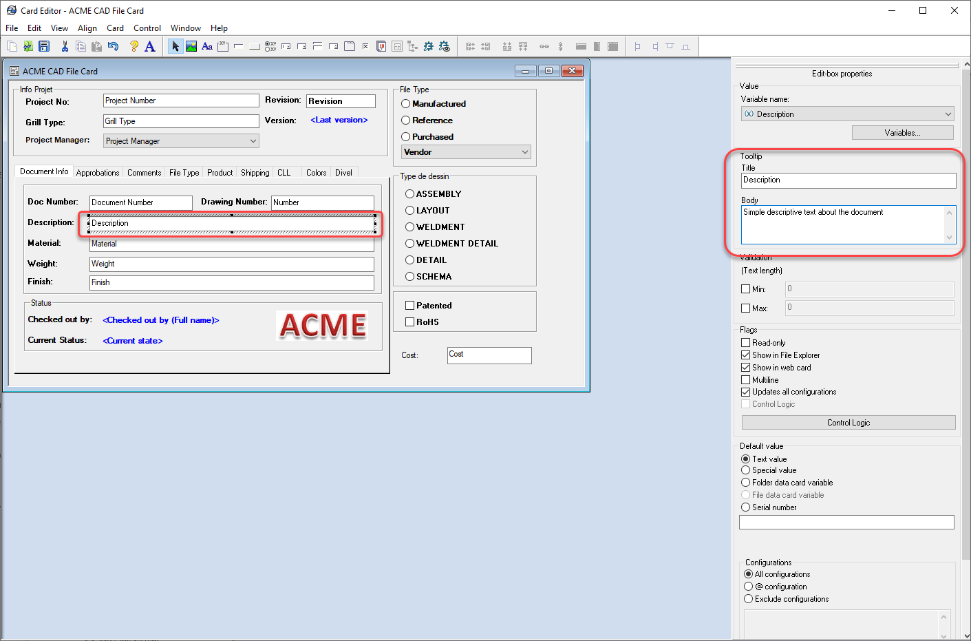
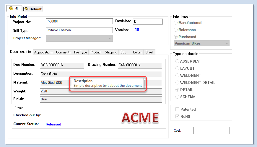
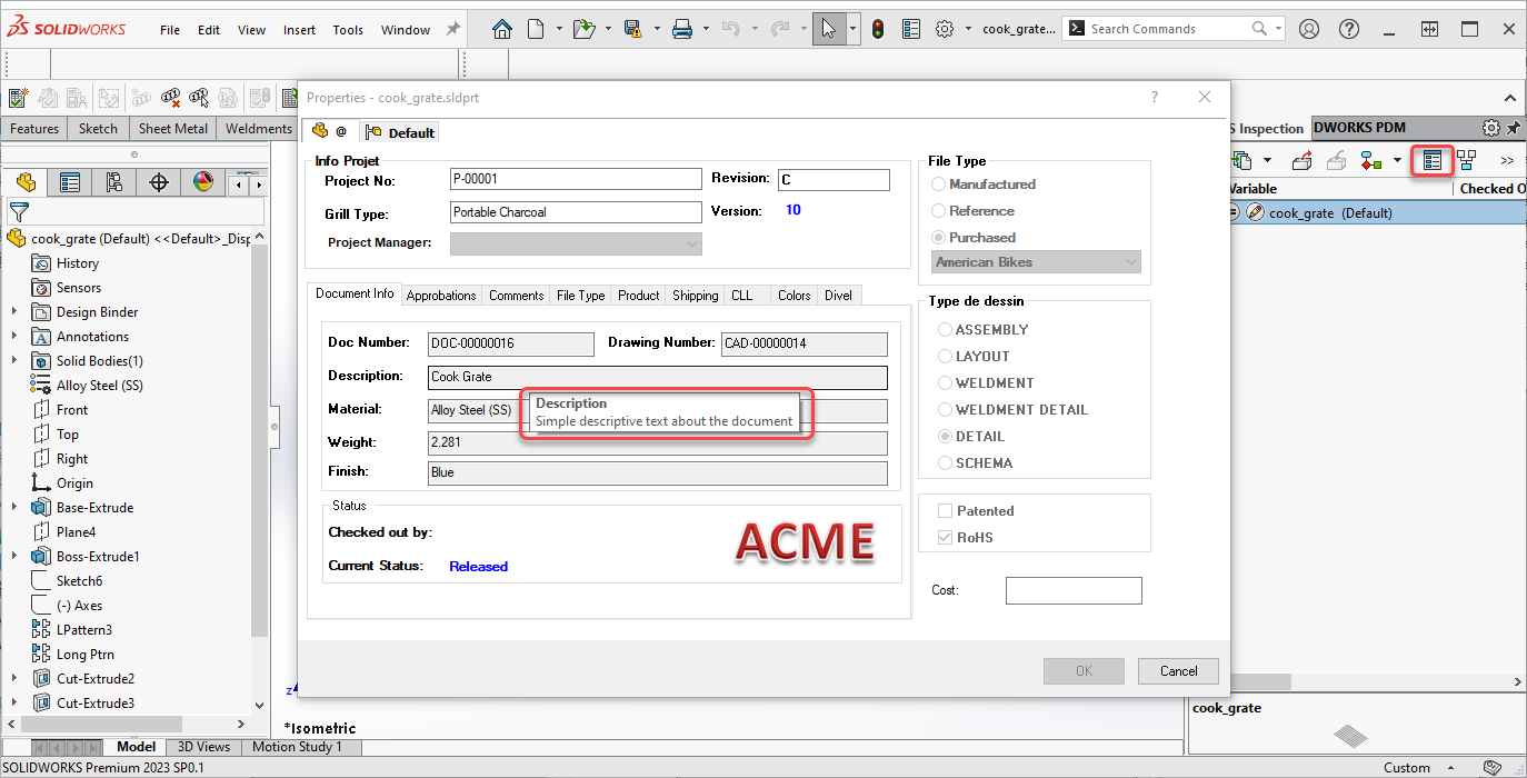
    Starting with SOLIDWORKS PDM 2023, you can now add a tooltip to your data card fields. These tooltips will show up when you hover over the fields when available. This gives you users more precise information about what to enter in these fields.


    In the data card editor, simply select the command onto which you want to attach a tooltip. Once selected, you will find the Tooltip fields in the command properties, to the right of the screen. Simply add a title and the tooltip text you wish to attach to the command:


    image006


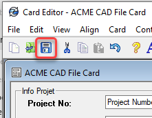
    Once you are finished with the data card modification, don’t forget to save the card by clicking on the blue disk at the upper left of the data card editor:


    image007

    The result will be visible when a user hovers their mouse over the data card field in Windows Explorer:


    image008


    The tooltip will also be visible from a data card from within SOLIDWORKS:


    image009

    Improve Data Entry with SOLIDWORKS PDM Tooltips

    Adding tooltips to SOLIDWORKS PDM data card fields is a simple way to give users clear instructions directly where they need them. By explaining what information should be entered, tooltips can reduce errors, improve consistency, and make data cards easier to use in both Windows Explorer and SOLIDWORKS.

    For more help configuring SOLIDWORKS PDM data cards and improving your workflows, contact the Solidxperts team.

    X_green_halo

    Any questions? Need help? Ask one of our experts.

    Whether you’re ready to get started or just have a few more questions, you can contact us toll-free:

      3DEXPERIENCE SOLIDWORKS 2023 WHAT’S NEW

      BLOG

      3DEXPERIENCE SOLIDWORKS 2023 WHAT’S NEW

      [techtips_featured_image_shortcode]

      ASSEMBLIES

      Optimization of lightweight / resolved :

      Lightweight supports part mass and similar properties.

      Auto repair of mate references

      Improved assembly cut feature

      Highlighting for overwritten BOM cells

      Specify the default BOM part number (as either Document or Configuration name)

      Improved STEP export

      Preview of Replace Component with instance(s) to replace controls

      Color option for Explode Lines

      Specify affected configuration(s) for skipped instances in patterns.

      Ability to suppress magnet mates & related connection points

      Override computed mass or cg values with Design Table entries

      Assembly feature propagation blocked from affecting Toolbox parts

      Assembly patterns with skipped instances are easier to configure.

      Replace component improvement, better options for instances, and more.


      COMPOSER

      View Collections capability

      Updated import file format support

      Support of Pro/E, CREO & STEP meta properties


      DRAWINGS

      Component Name display choices made in part or assembly feature tree are reflected in the Drawing view pallet.

      Detached Drawings are fully discontinued and replaced with Detailing Mode

      Detail drawings of assembly components can be opened directly from the assembly drawing without opening respective geometry files.

      RMB graphics area, BOM cell, or drawing view tree.

      Not fully supported for Detailing Mode.

      BOM table overrides can now have a specific highlight color. (default Sys Opt is black)

      RMB selection is provided to restore to original values per cell, row, column, or the entire table.

      Highlight color only shows when the table is selected. (not for print and so on)

      Quantity indicators now allowed for Auto Balloons as well as manual balloons.

      BOM tables can now be filtered like a spreadsheet, and the auto balloons update to match.

      Do not combine filtering with the hiding of columns or rows.

      Transparent component support for HLR / HLV views improved to match with ISO standard 128-2020.

      Check box option in view PM or in Document Properties.

      Hole Tables now support punches and slots in addition to holes (a top 10 ER).

      GeoTol symbols can be limited to the current drawing standard.

      Vector translation modifier now supported in GeoTol frames.

      Dynamic Profile Tolerance supported per ASME Y14.5-2018


      EDRAWINGS

      Assembly display and publish improvement

      Model Configuration support for eDrawings mobile apps

      Publish support for Display States in eDrawings

      Display Style improvements

      File type version enhancement

      Multi-language support for eDrawings to web HTML

      Inch fractional measurement units


      ELECTRICAL

      Support for hybrid drawings – schematics & tables combined on 1 sheet

      Component dynamic connection label annotations supported in schematics

      Ability to set 3D part mass props from Electrical Schematic properties (per spec sheet)

      Improved condition icons for 3D electrical components (inserted, connected, and so on)

      Open ended wire support in schematic. (for pigtails or wire on install connections)

      Schematic sheets support more image types. (tiff, png, jpg)

      Deleting Component can force deletion of related symbols

      Reset for Dismissed Messages

      Excel Automation Improvement

      Origin -> Destination specification


      FLOW

      Mesh Boolean Operation – allows meshes to create even when base geometry is imperfect

      Turbidity Factor – for solar radiation effects, accounts for polluted or storm-filled atmosphere

      Reduces heat effects in some cities versus open desert

      Plot Cropping – (cut, mesh, surface) restrict the display to a particular material or fluid domain

      Tangential & Radial Velocity effects for Fan Curves – property allows a more thorough definition of fan performance

      Heat conductance on porous media as dependent on specific mass flow – increases accuracy for compressible fluid and gas flows.

      Project Tree Sorting – alphabetically or chronologically

      Transient Explorer export options – export results by time range, or for the active time moment

      Transient Explorer custom parameters – for better visualization

      New Study Goals –

      Total Energy Balance

      Volumetric Heat Generation Rate

      Radial & Axial Velocities

      Flux Plots with total energy balance display

      Performance – Mesher and Solver operations are now faster due to improved memory use management


      IMPORT/EXPORT

      Large assembly export supports individual STEP file generation

      Textured *.obj file import is improved


      INSPECTION

      AddIn – Balloon Sequence configurability

      With multi-sheet options

      Addin – Balloon Drawing Sheets Separately

      Addin – Export sheets as separate PDF files

      Addin – Export reports as separate Excel files

      Addin – Inspection Manager with Characteristic tree view

      Standalone – Autoballoons for PDF drawings

      Standalone – Manual Extract replacement for OCR (better results)

      Machine Learning support for 2D PDF

      Sheet selection mode for multi-sheet drawings

      Export Reports to individual Excel files

      Balloon Sequencing


      INSTALLATION & SNL

      Flow Simulation HVAC and Electronics Cooling modules can now be independent AddIns and the SNL licenses loaded or unloaded as needed rather than always being reserved with each use of Flow Simulation.

      Term licenses now show pending expiration in the SNL manager and can be renewed or reactivated by individual serial numbers.

      All products will now have a term license option.


      MANAGE

      Automatic update of mapped linked records

      New From option for data fields

      BOM field comparison (linked vs primary)

      Variable Driven BOM Qty support

      Cancelled Tasks reflect properly in capacity planning

      Task Board Display


      MBD

      View control for all dimension types, not just DimXpert annotations

      Hole Tables support multiple views

      Dimension Extension Line

      Datum Feature editing

      Wedge as geometric & annotation feature

      Support for ISO Tolerance modifiers


      PART MODELING

      Support of Move/Copy Body translation or rotation values in Equations and Design Tables

      Defeature now supports creating derived configurations for parts as well as assemblies.

      Dimension support in Move/Copy Body

      Allowance of Library Feature Errors – click [Yes] to accept the feature errors, and then correct them after the insertion in the current part.

      Coordinate Systems are now valid for selection in more commands – such as, 3D sketch operations, 2D sketch dimensions, mirror, and during select other

      Single stroke font support in Wrap Feature sketches (Scribe wrap type)

      OLFSimpleSans – is installed by SOLIDWORKS

      Hybrid Mesh-BREP modeling improvements

      Extended feature support

      Section View creation through Axis

      Euler method rotation is now allowed for Move/Copy Body, and it can be set per configuration.

      Move/Copy Body translations can also be set per part configuration now.

      Global variables or equations can now be used to drive the Move/Copy Body values.


      PDM

      HTML customization for Notification templates

      File Version Upgrade Tool – supports overwriting latest version

      Streamlined UI for check-in/out

      New options to manage Deleted Users

      Transition Actions configurable by user account and properties thereof

      Tooltips can be added to Data Card fields

      Improved Data Card controls

      Copy & Paste display text to variable fields

      Buttons can have user-lookup data (names, AD fields, and so on)

      Better image file support. (jpg, png)

      Logging of File Retrieval Operations ([x]Get log property at PDM Pro server)

      Display source Groups for Inherited User Permissions

      All data transfers encrypted to/from the server

      STEP export task enhanced for 242, or shattered assembly components.

      eDrawing files in the vault support thumbnail previews in the explorer panel.

      Autologin option for vault Admin. (setting in the admin tool at a local machine)

      Archive Server & Database Server improved in higher latency environments (Azure, AWS)

      Private State folder visibility option for non-Admin users.


      PERFORMANCE

      Level of Detail system option to improve graphics changes (zoom, pan, rotate) for most view types.

      Faster save operations for large assemblies with some amount of unchanged components.

      PDM is faster and more efficient in high-latency networks.

      PDM file version upgrade tool operates faster.


      PLASTICS

      Material Database & Material Grade additions

      Material Database UI improvement

      Report enhancements


      ROUTING

      Improved electrical flattening and manufacturing drawings

      With better connector tables.

      Multi-wire circuit splice support.

      Design Library auto-style clips added.

      Routing Library Manager performance and usability improvements.

      Harness diameter & length are show in an electrical route property manager.

      Accommodates and displays unused cores.

      Auto Route improvement for discrete wires


      SHEET METAL

      Deviation sensor

      You can create a sensor to alert that the sheet metal exceeds a bounding box size. (max length, width, area, blank area)

      Symmetrical Thickness

      Specifies material to be applied symmetrically from the base flange sketch.

      Gauge Values in Cut List properties (and drawing notes)


      SIMULATION

      Improved surface to surface bonding interactions (allowed for non-contacting faces)

      For ignoring set screws, pins, etc.

      Diagnostic Tools

      Linkage Rod Connector

      Penalty Stiffness Control for Contact (up to 50% solve)

      Solver improvements

      Underconstrained Body management (Simulation Professional & Premium)


      SKETCHING

      Elipses now have options to create construction lines across the axes.


      SOLIDWORKS CAM

      Barrel Tool Support

      Improved Leadin & Leadout Calcuation for contour milling

      Lines Only Option for VoluMill Toolpath

      Tolerance Based Machining improvements


      STABILITY

      90% reduction in customer reported crash SPRs.STRUCTURE SYSTEMS

      Corner Trims of similar corners by Group, with Connection Plates by Group

      Configuration specific weldment member sizes

      Alignment of Custom Properties Attributes (for matching with 3DEXPERIENCE attribute types)


      USER INTERFACE

      Comments in SOLIDWORKS files now have additional color and formatting options.

      Comments can be set to Show At Start when files are opened.

      Improved Restore Default Settings options and behavior.

      Improved behavior of Copy Options Wizard.


      VISUALIZE

      Color Picker tool improvements

      DSPBR Materials Support

      Import Options (grouping) are easier for SOLIDWORKS files

      Stellar Physically Correct illumination render

      PhotoView 360 to be retired at 2023 sp5.

      X_green_halo

      Any questions? Need help? Ask one of our experts.

      Whether you’re ready to get started or just have a few more questions, you can contact us toll-free:

        How the Concept Cars of Tomorrow Are Made With 3D Printing

        BLOG

        How the Concept Cars of Tomorrow Are Made With 3D Printing

        [techtips_featured_image_shortcode]

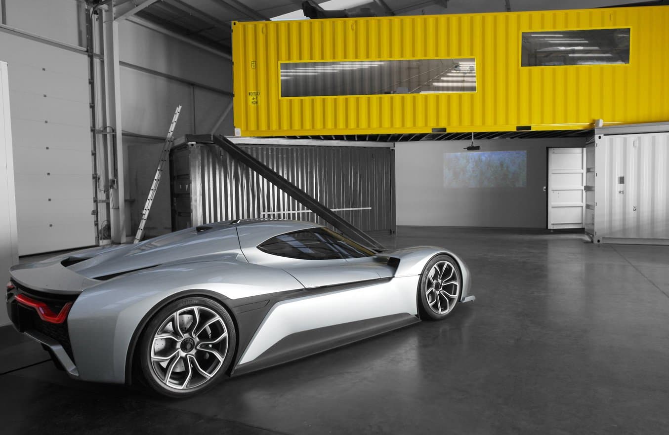
        Located in the heart of the UK’s auto industry, Vital Auto is an industrial design studio with deep expertise in automotive design. The company’s illustrious clientele includes many of the major automotive manufacturers, such as Volvo, Nissan, Lotus, McLaren, Geely, TATA, and more.

        “Clients typically come to us to try and push the boundaries of what’s possible with the technology available,“ said Shay Moradi, Vital’s VP of Innovation & Experiential Technology. When manufacturers don’t have time for experimentation themselves, they rely on Vital Auto with any kind of challenge to turn ideas, initial sketches, drawings, or technical specifications into a fully realized physical form.

        Read on to learn how Vital Auto—a customer of Formlabs’ fastest growing UK reseller, SolidPrint 3D—creates high-fidelity prototypes and concept cars, rapidly working through iterations using a variety of advanced tools, including a large fleet of Form 3L and Fuse 1 printers.


        The Making of a Concept Car


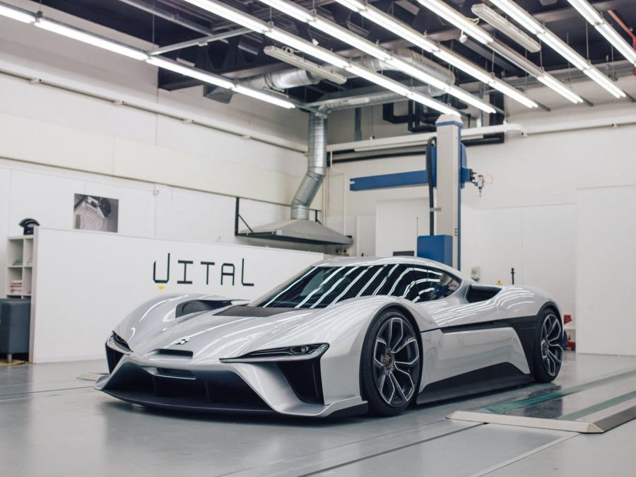
        Vital Auto was founded in 2015 when three friends got together, quit their jobs, and decided to set up a shop—fittingly—in a garage. One of the first contracts the company took on was for the NIO EP9 supercar concept, which instantly set the team on a course to producing extremely realistic, high-fidelity vehicular prototypes.

        Depending on the client’s request, the team will start anywhere from simply a sketch on a piece of paper to an already designed vehicle. They develop cars from a blank sheet and design all the mainframes, all the exterior and interior elements, open/closings, and interactive elements. With five to 30 people working on a single concept, a typical project could take anywhere from three to 12 months.

        During this time, a typical show car goes through up to a dozen core design iterations, and within those, there can be further iterations of smaller components until the design meets the expectations of the customer.

        “It’s all well in our industry to look at virtual properties as a means of evaluating a product before it goes to market. However, I think there’s always going to be a place for physically manufactured objects as well. There’s nothing that beats the sensation and feeling of holding an object in your hands with the correct weight, with the correct proportions, and the dynamics of how the physical environment changes your perception of that physical object,“ said Moradi.


        “Most of our customers will come to us with a new idea, an innovative idea, and something that’s never been done before. So the challenges for us are new every single day and they’re endless,” said Anthony Barnicott, Design Engineer in charge of additive manufacturing. “These challenges can range from, how can we produce this number of parts in this amount of time to, how can we make a sustainable product or how can we make a part that achieves a particular weight while still achieving a particular performance.”

        While traditional show cars are normally made just from milling clay, the team also uses three- and five-axis CNC milling, hand forming, hand clay modeling, and GRP composites. These traditional processes are, however, often not ideal for producing the custom parts required for one-off concepts.

        “We’ve used 3D printing from day one. We wanted to introduce it to our manufacturing processes, not only to reduce costs but to give the customer more diversity with their designs and their ideas,” said Barnicott.

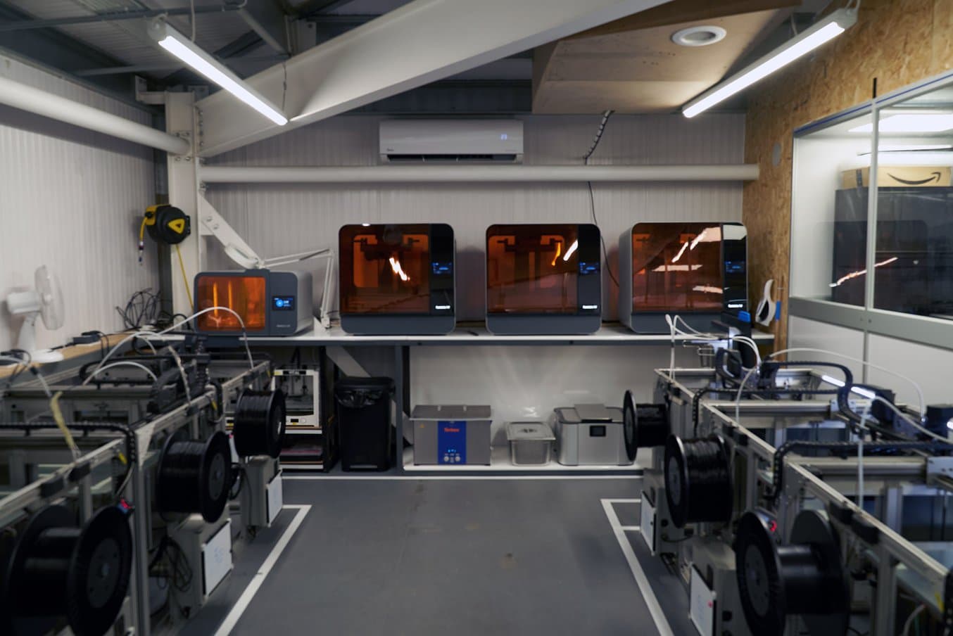
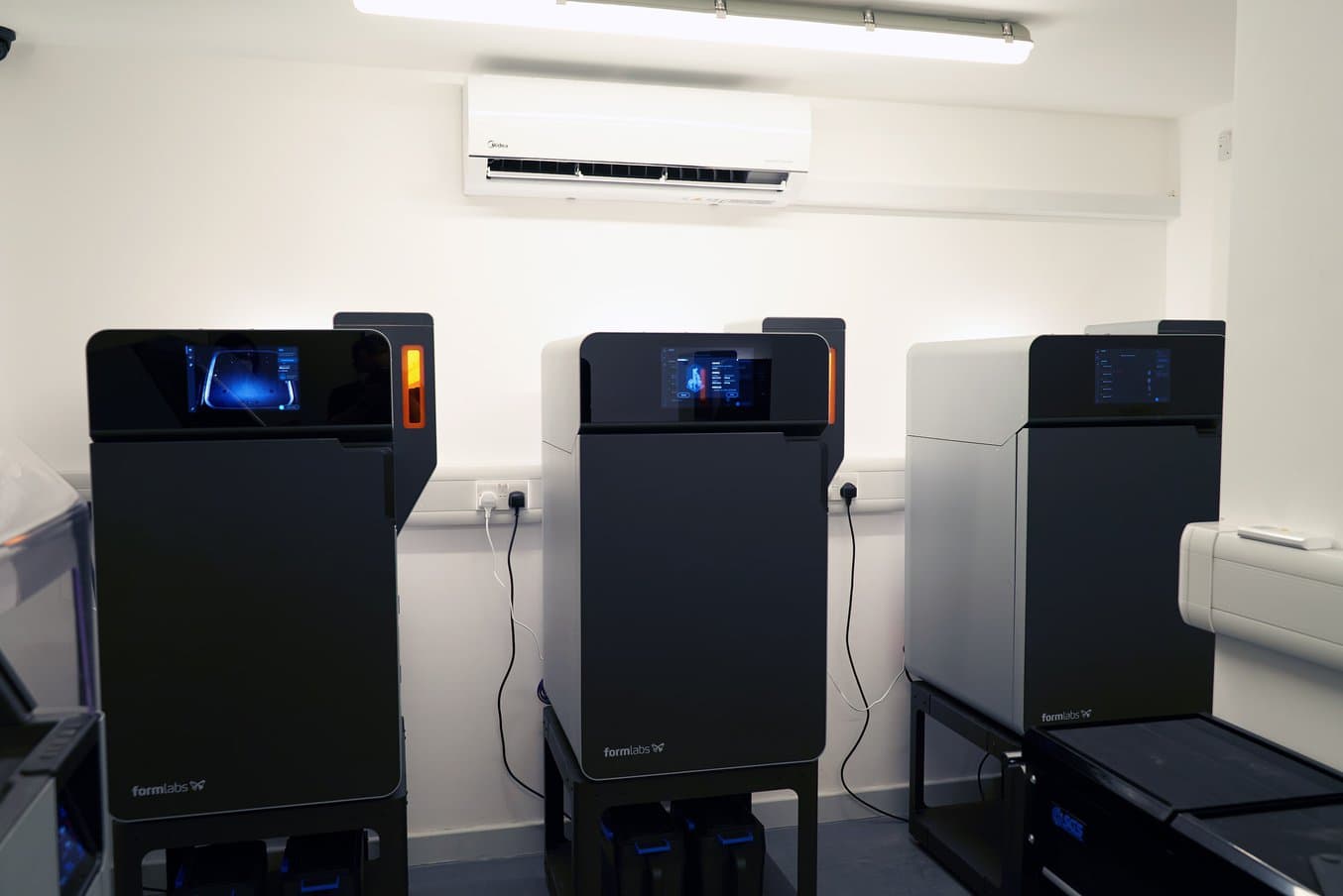
        Today, Barnicott runs a whole 3D printing department, including 14 large-format FDM printers, three Formlabs 3L large-format SLA printers, and five Fuse 1 SLS printers.

        “In terms of capacity, all those printers have run 100%, 24/7, pretty much since day one. We use these printers for all areas of our concepts and designs. Typically, we would use the Fuse 1s for our production-based parts and we would use our Form 3Ls for our concept-based parts,” said Barnicott.


        Manufacturing Complex Designs From Multiple Materials With the Form 3L


        “We use the Form 3L machines for anything that is an A-class finished surface. So typically in an automotive environment, and interior where you have parts that are not being trimmed with leather or Alcantara or some sort of cloth material. Formlabs materials give us a nice, smooth finish for our painters to work with, we can use these parts straight out the printer, straight onto a vehicle,” said Barnicott.

        “What interests me most about the Form 3L machines is their versatility, the ability to do a material change in less than five minutes and the variability of those materials going from a soft, flexible material to a hard and rigid material for us is priceless,” said Barnicott.


        The team uses the Form 3L’s with multiple materials for a wide array of applications, for example:


        Air Vents


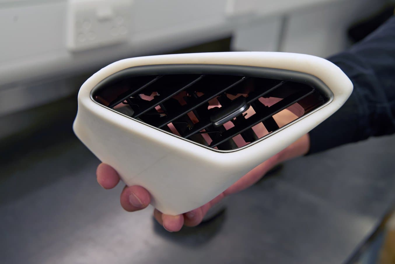
        “It’s a common challenge for us as a business where customers will approach us with a proprietary product and want to encase it in their own design. Once, a customer approached us with a proprietary air vent from another vehicle that they wished to have inside their own interior. We used 3D scanning technology to reproduce this part digitally and then created an external skin. We first produced this in the Draft material to test out the design and allow the customer to verify it. From there, we moved to the White material to produce a production-ready part.”


        Switch Packs


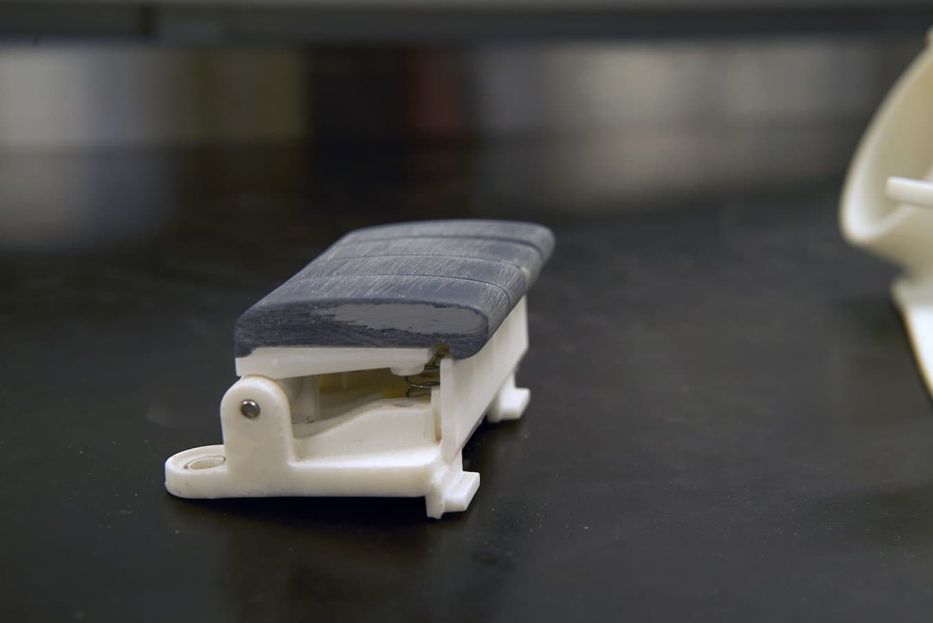
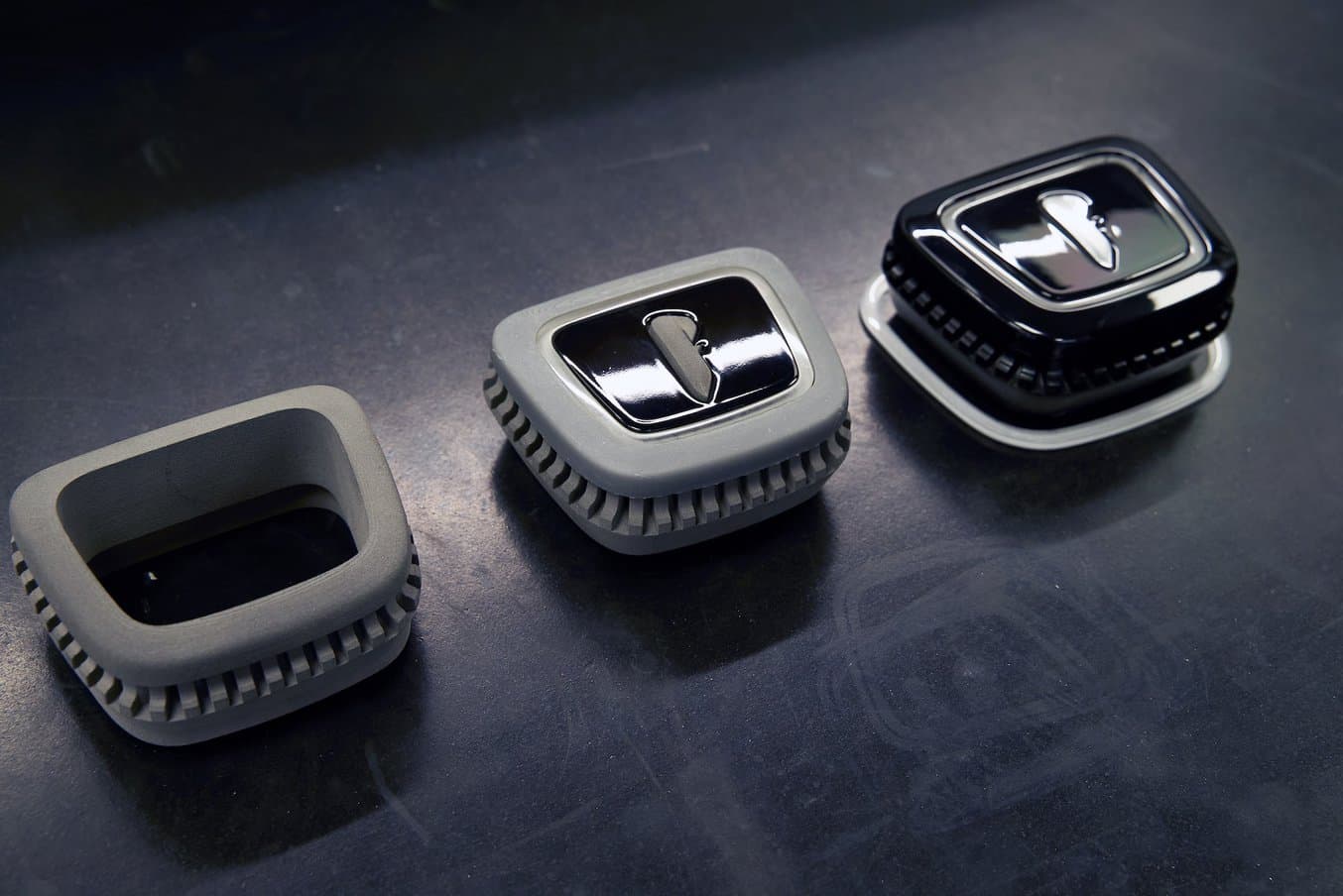
        “When working with incredibly intricate designs, such as small switch packs, what we’re able to do is use multiple materials to achieve a mechanical product that not only functions correctly but can be used in a real-world environment. [For these switch packs], we combined harder materials, such as the Tough 2000 for the top surface, with the lighter, more cost-effective materials for the internals.”


        Door Seals


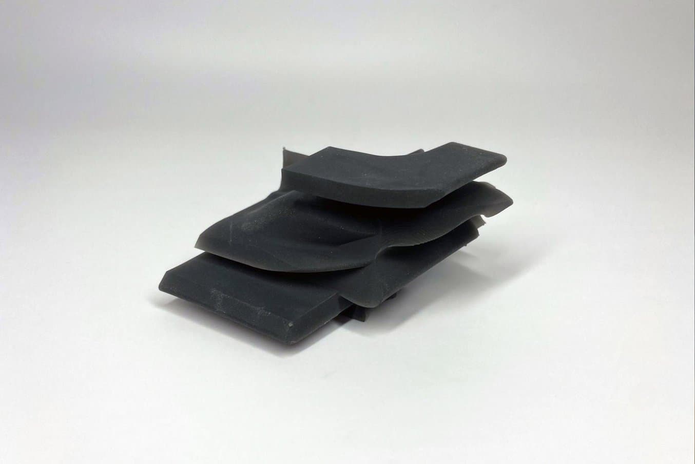
        “Typically, door seals for automotive applications can be incredibly costly to produce. there’s simply no other way other than extrusion molding to produce them. This comes at, not only a very large tooling cost but also a long lead time as well. We were able to experiment with one of Formlabs’ newest materials, the Flexible 80A. The Form 3L enabled us to produce sections of this door seal overnight to test various geometries and was printed within 50 microns of the actual design.”


        Having the Form 3L empowers the team to produce multiple iterations of parts in most cases within 24 hours. They ended up buying three different machines so they could produce up to three different iterations of a part at the same time, even using three different materials. They can then pass on the cost savings to the customer or offer more value by showcasing multiple design options for the same price.

        “One of the beauties of using additive manufacturing is the compression of a timeframe. So what do you do in that span of time that you have freed up? We sort of seeing it as extending the possibility space into imagining alternatives, into adding more iteration loops in the process,“ said Moradi.

        “There are many products we produce that we simply wouldn’t be able to without our Form 3Ls. With some of the most advanced manufacturing techniques, such as seven-axis CNC machining, we’d be able to produce these parts, but it would come at a huge compromising cost,” said Barnicott.


        Complementing CNC Machining for Mechanical Parts With the Fuse 1

        “The Fuse 1 one was our first venture into SLS technology. As a small business, this is a technology we thought we would never be able to have on-site. With the Fuse 1, not only do we have one of the machines, but we actually have five of the machines on the site. What these machines enable us to do is produce structural mechanical parts very quickly, not only for testing but for physical applications in most of our concepts. This process would have typically been done by CNC machining, either on our site or off-site, depending on the geometry, and we would have to wait two to four days to get the parts in our hands. The Fuse 1 enables us to cover all of this on-site and have parts in our hand in most instances, less than 24 hours,” said Barnicott.


        The team mainly uses the Fuse 1s for mechanical parts, such as door hinges, door handle inners, door internals, and structural applications. They can use these parts straight off the printer, with minimal finishing. Some of the applications where the team used the Fuse 1s include:


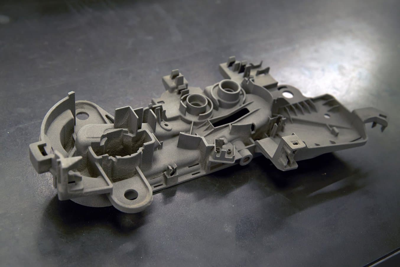
        Air Duct


        “A lot of automotive interior parts can be incredibly tricky to produce without going down the traditional injection molded route. Items such as internal air ducts and vents, items that are never seen, but yet require a large cost to produce. We use the Fuse 1 to produce these parts. It allows us to be much more versatile with the designs we put in the vehicle without incurring the large costs that they would typically have.”


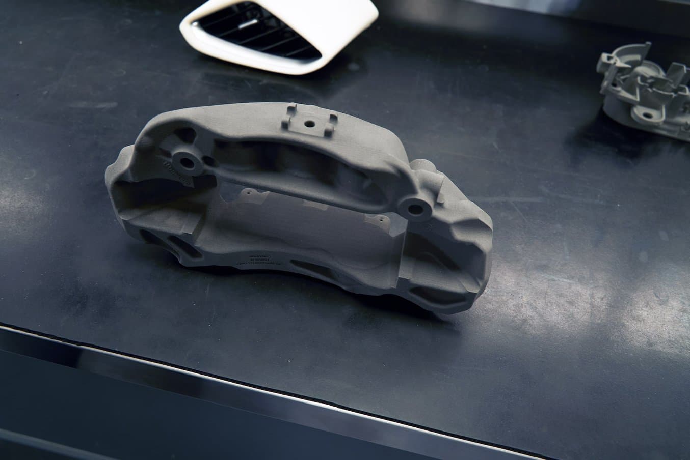
        Brake Caliper


        “Sometimes we produce parts whereby the customer simply wants to see what their brand will look like on a specific part. That means we have to produce a part rather quickly so we can apply their brand to it. We use the Fuse 1 to produce these parts, such as a brake caliper, and we can produce the logo in different areas of the caliper in different colors for the customer to review.”


        Interactive Concept for a Supercar


        “3D printing has allowed us to combine both the SLA and SLS materials to work our way through design iterations on a specific project. This allows us to quickly produce multiple iterations, combining both processes, using them for their specific properties, to achieve a final design. This can be anything from mechanical parts to clear parts to check their optical quality and output.”


        While it’s often said that additive manufacturing is here to replace subtractive manufacturing, the Vital Auto team sees benefits in combining different technologies to leverage their best qualities.

        “We use the two processes together to help support each other. We have many parts where we would use subtractive manufacturing and then use additive manufacturing to produce all the finer details. This allows us to have a much more cost-effective way of producing a lot of our concept models,” said Barnicott.


        Creating High-Fidelity Concept Cars With 3D Printing


        “The progression in technology and 3D printing over the last 10 years is phenomenal. When I first started, producing low-volume, niche vehicles, some of the products that we produce today would simply have been inaccessible. And not only am I able to produce these parts today, but I’m also able to produce them very cost-effectively, very quickly,” said Barnicott.

        3D printing not only helps the team create better products faster but also attracts new business. They found that many of their customers turn to them because they want to have access to the latest technologies and they want to have their components made using the latest cutting-edge materials.

        “There are certain things that you just can’t class as emerging technologies anymore. 3D printing is one of those things. It’s advanced to a point where everything that we produce is good enough for use in the final presentation stage with all the layers of making that we apply on top of that. 3D printing has gone from almost a novelty to becoming an absolutely inseparable part of what we do,“ said Moradi.

        X_green_halo

        Any questions? Need help? Ask one of our experts.

        Whether you’re ready to get started or just have a few more questions, you can contact us toll-free:

          How to add the Thickness of Sheet-metal as gauge in a Layout

          BLOG

          How to add the Thickness of Sheet-metal as gauge in a Layout

          [techtips_featured_image_shortcode]

          In this tech tips we are going to find out how to add the Thickness of Sheet-metal as a gauge in a Layout:

          When one designs products with sheet metal, the industry uses the thickness values from a gauge table. For example, an 18 gauge is equivalent to a thickness of 0.0359 for a steel part. It is possible to use this kind of table in the sheet-metal function of Solidworks.

          Continue reading “How to add the Thickness of Sheet-metal as gauge in a Layout”

          Printing & Post Processing of Replica Models with Markforged

          BLOG

          Printing & Post Processing of Replica Models with Markforged

          [techtips_featured_image_shortcode]

          By Gregory Bejtlich – Application Specialist at SolidXperts

          Despite the many advances in 3D printing technology, additive manufacturing continues to be a monochromatic industry. Conventional FFF (FDM) and SLA printers are limited to printing one color at a time, but what do you do when you need more? Adding a splash of color to your model improves aesthetics and highlights key details through the pre-production phases.

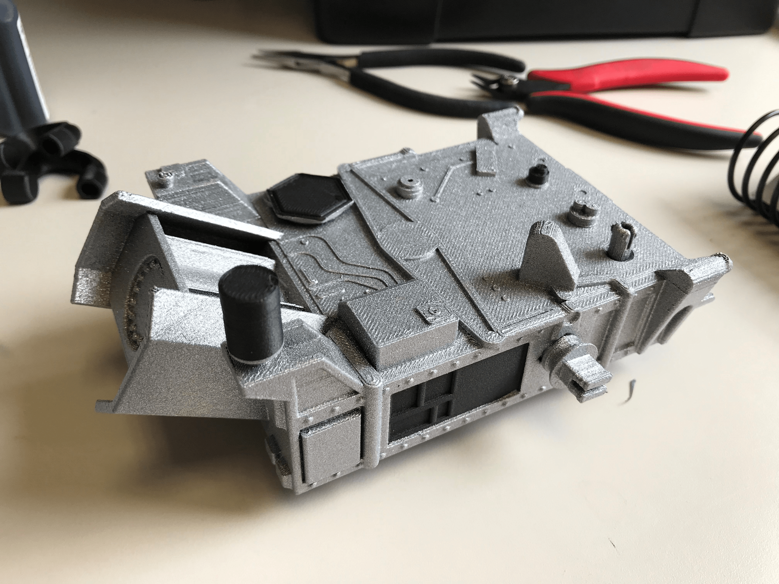
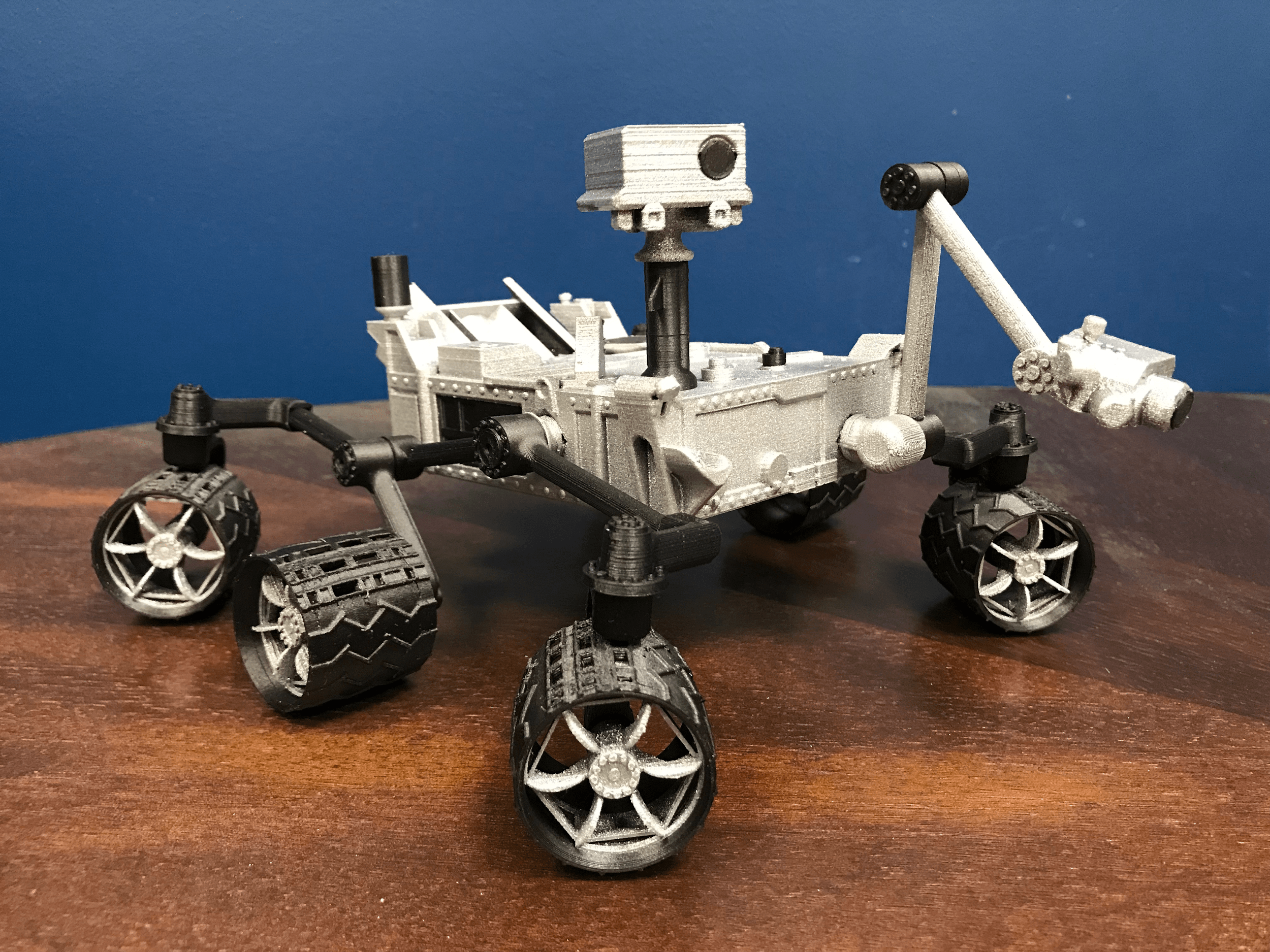
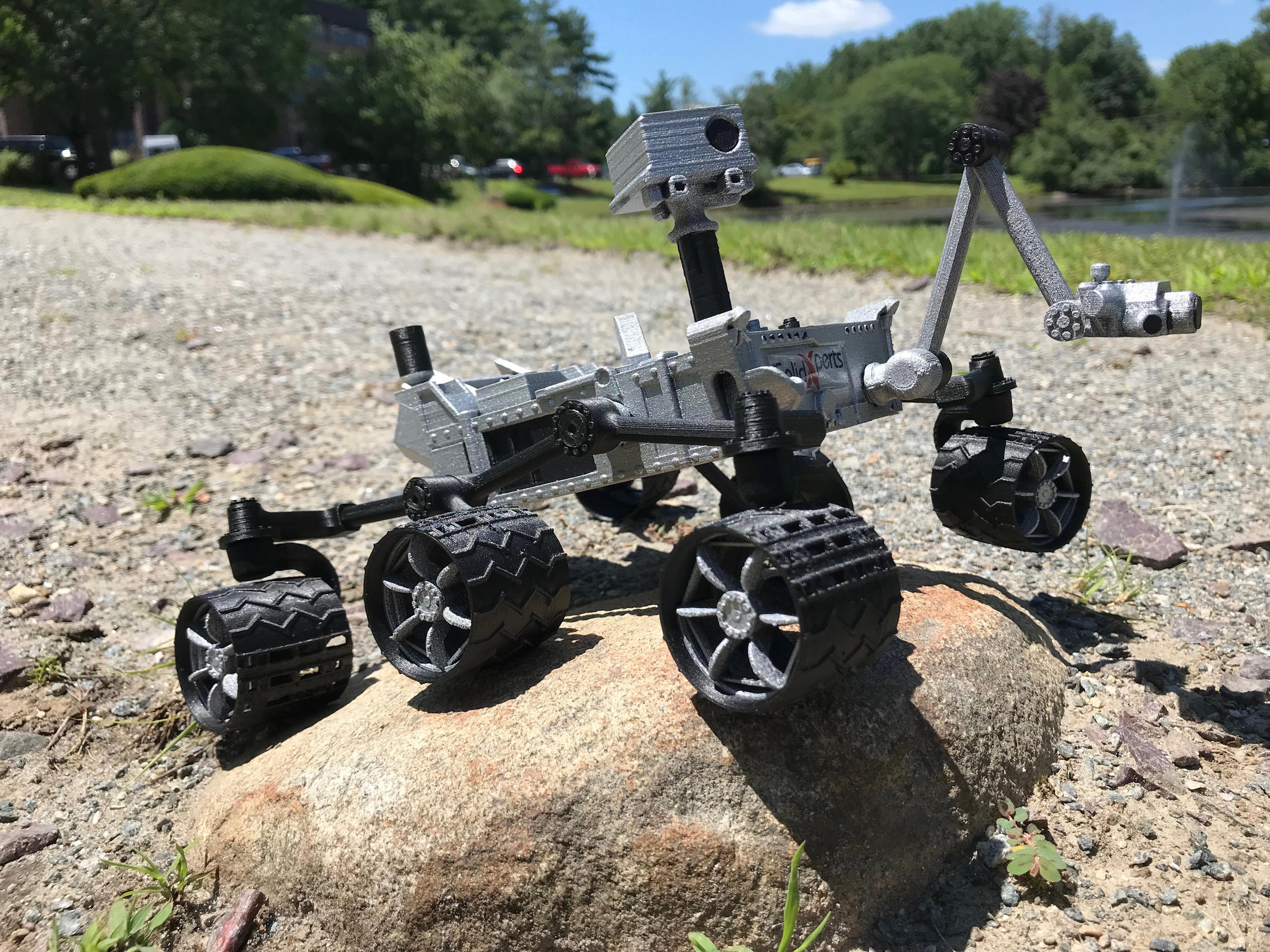
          Today we are looking at the printing and post-processing of a Mars Rover replica. Since 2014 NASA has been releasing 3D models to their public database, including files optimized for 3D printing. Some of our favorites include the 1:200 scale SOFIA, also known as the “black-hole hunting” Boeing 747SP, and the conceptual Titan Submarine tasked with exploring the methane seas of Saturn’s largest moon.

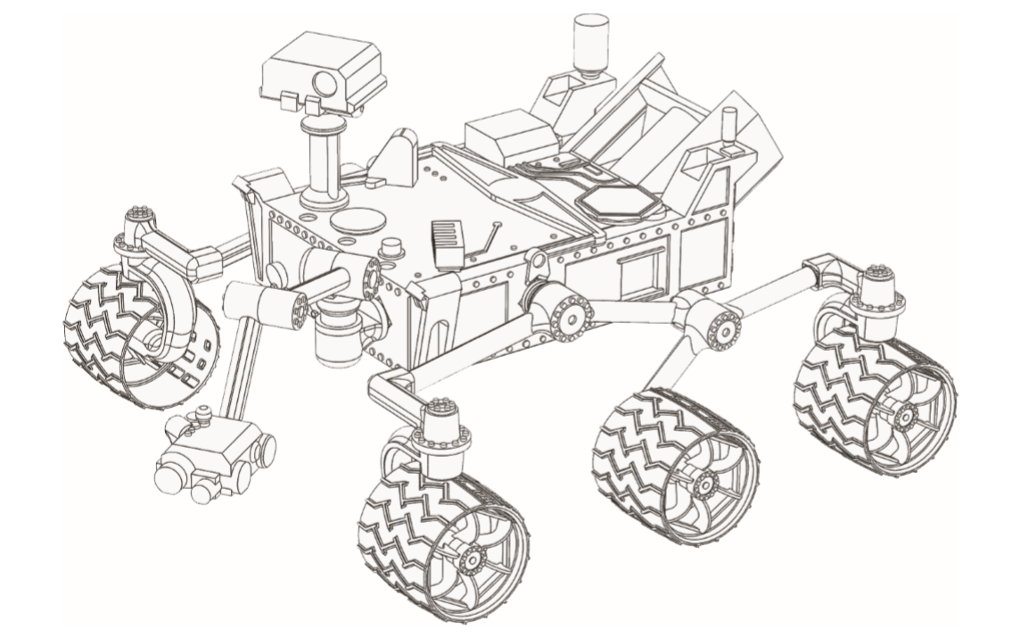
          Despite these interesting models, our favorite must be the Mars Curiosity Rover. Launched in 2012, the Curiosity Rover has been researching the Gale crater in search of microbial life and water. The 3D models are free from NASA and can be found on their “3D Resources Page”.

          Download the files here

          Detailed Curiosity Model (Large) – Build Instructions

          The file set includes twenty-one unique components and four pre-nested files for your printing convenience. The models are designed for FFF printing and include “support free” features, e.g. diamond/arched cutouts angles less than 45°, and pre-oriented parts.

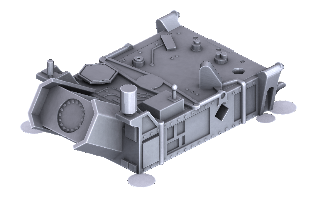
          Curiosity Rover Body (no support needed!)

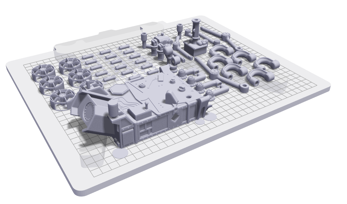
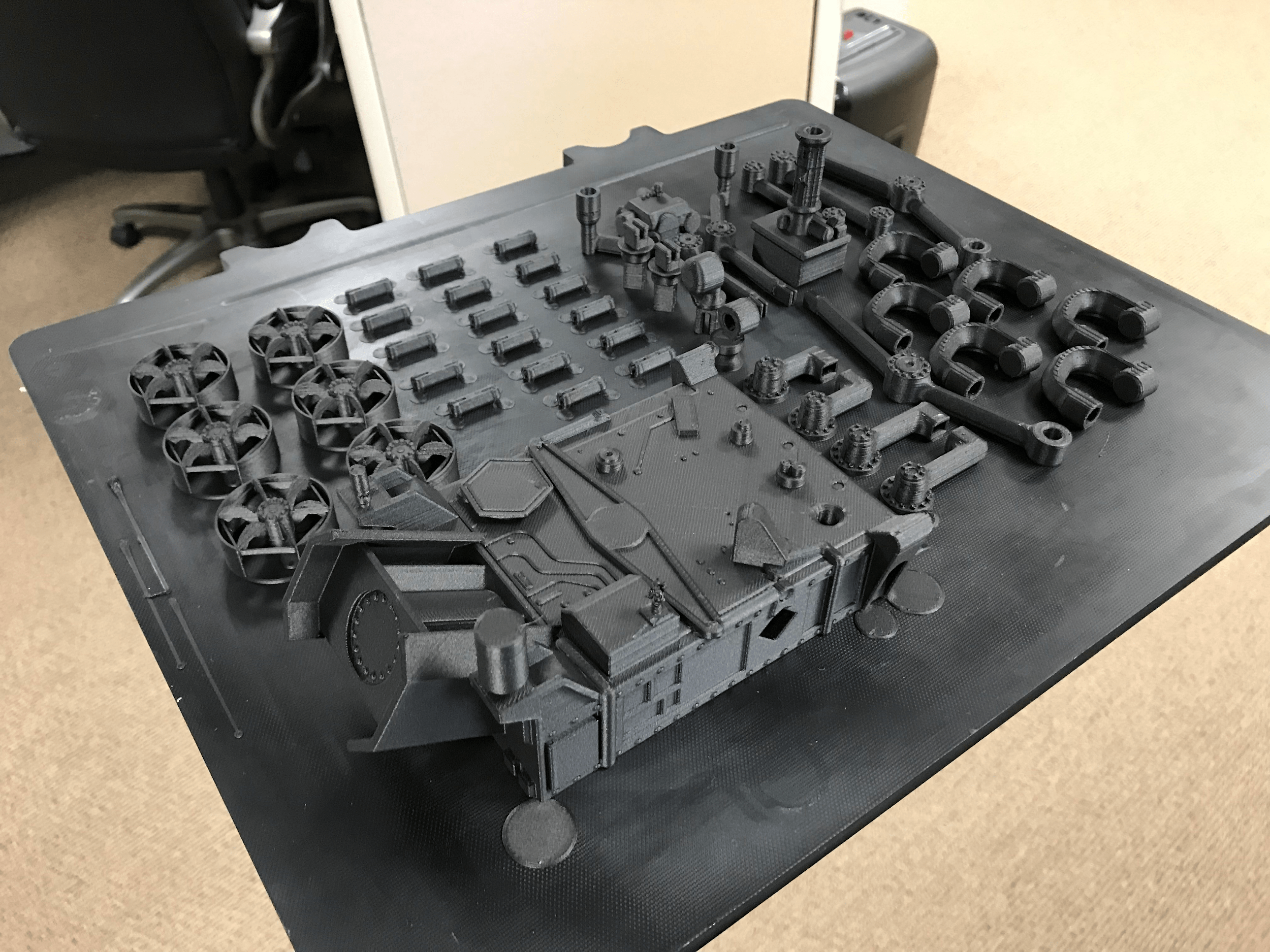
          Our go-to printers for the rover replica were the Markforged Mark Two and the Industrial X7. Note: The 200 µm resolution and filament used for this print can also be accomplished with the base series Onyx One. The flagship material for Markforged printers is a nylon-carbon fiber blend called Onyx, which is known for its rigidity, matte black appearance, and strong chemical resistance. To make this print more manageable, we fit as many parts as possible on the X7’s massive build plate and fine-tuned the settings. The default Eiger settings work best, but the resolution was reduced to 200 microns for a faster print. In total, the “time to part” was 39 hours with a cost of $58.36.

          Eiger X7 Buildplate

          Build Volume: 12.9in x 10.63in x 7.87in

          What made these models ideal for additive manufacturing? Minimizing the amount of support material necessary keeps the surfaces smooth and requires minimal cleanup. Strings and excess material were removed with a fine point blade, and rough surfaces were given a light 220-grit sanding. While the 200 µm layer height prints more quickly than the higher resolution layers, the striations become more apparent on angled and domed surfaces which can be filled with filler or primer as necessary. Geometry with greater curvature should be printed at a much smaller layer height (50-125 µm).

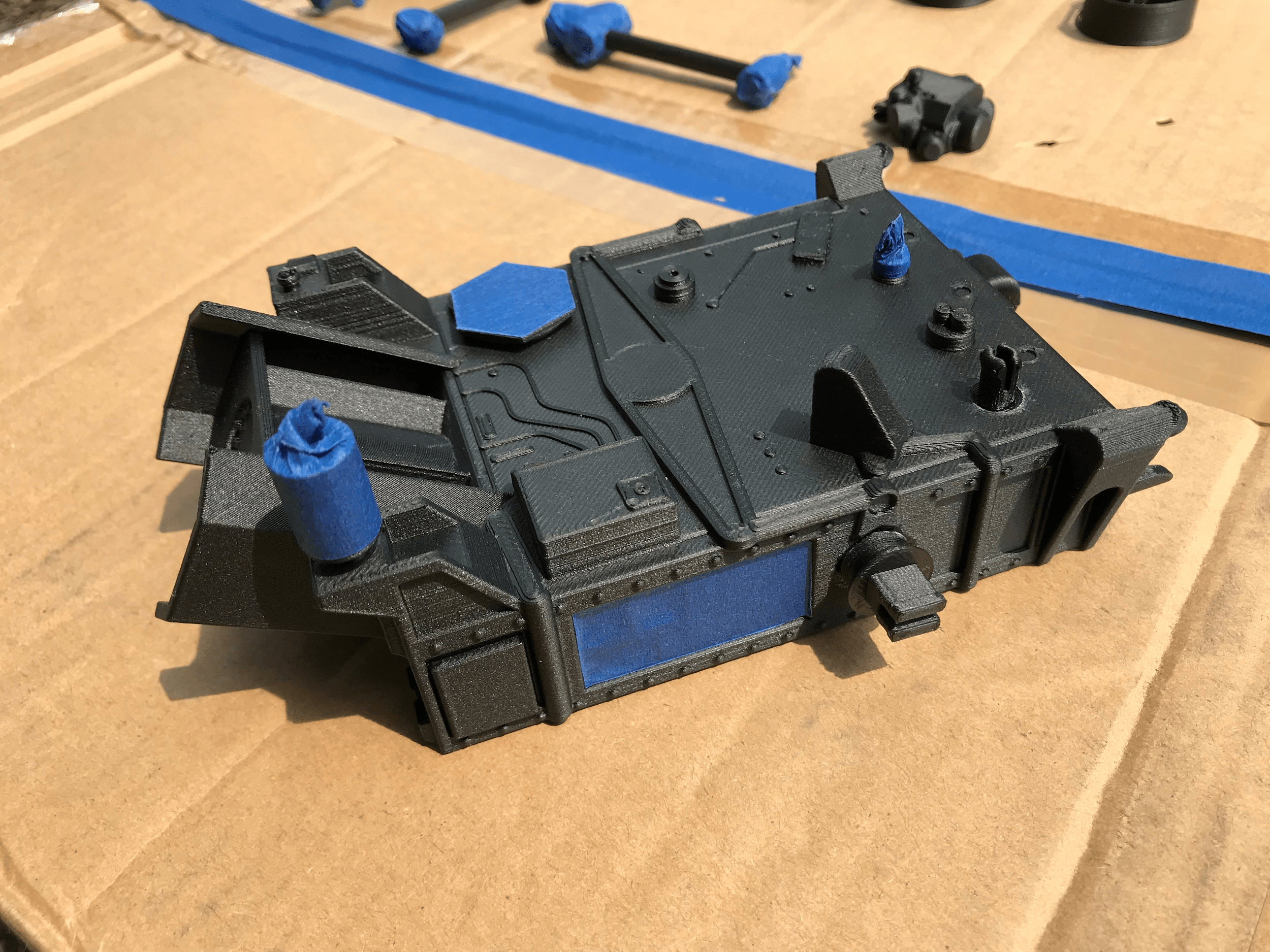
          Assembly and disassembly before painting are recommended as part interference or further clean-up may be required. Blue painter’s tape can be used to mask off a specific section or features retaining the black appearance underneath. Since Onyx is carbon black, a base layer of plastic primer is a must! Paint will adhere to the primer and will enhance lighter colors on the black surface. Our choice of paint is Krylon Fusion All-In-One which has both primer and paint and adheres well to Onyx. If the part will be subjected to harsh outdoors, a satin or glossy clear coat can help protect the finish.

          After drying in a well-ventilated area, carefully remove your masking tape and begin assembly. Many of the dowel pins included have a retaining lip and rotate freely. Other components such as the mounting bracket should be anchored with super glue. In general, gel super glue performs better than liquid as it fills gaps and has a longer set time. Markforged recommends Loctite 4861, but we’ve had success with many brands of gel super glue.

          Tip: If you desire further detail in your model, skip the spray paint and color the bolts and wiring with a fine-tip paint brush or paint pen.


          Finally, enjoy your print and take some photos!

          SolidXperts offers you the solutions to meet your needs and help you in all your daily challenges. For more information about Markforged 3D printers, contact us.

          X_green_halo

          Any questions? Need help? Ask one of our experts.

          Whether you’re ready to get started or just have a few more questions, you can contact us toll-free:

            Need to cancel the check-out of a file from another user on PDM?

            BLOG

            Need to cancel the check-out of a file from another user on PDM?

            [techtips_featured_image_shortcode]

            In this tech tip, we are going to find out how to cancel the check-out of a file from another user on PDM because this permission is no longer exclusive to the default Admin user:

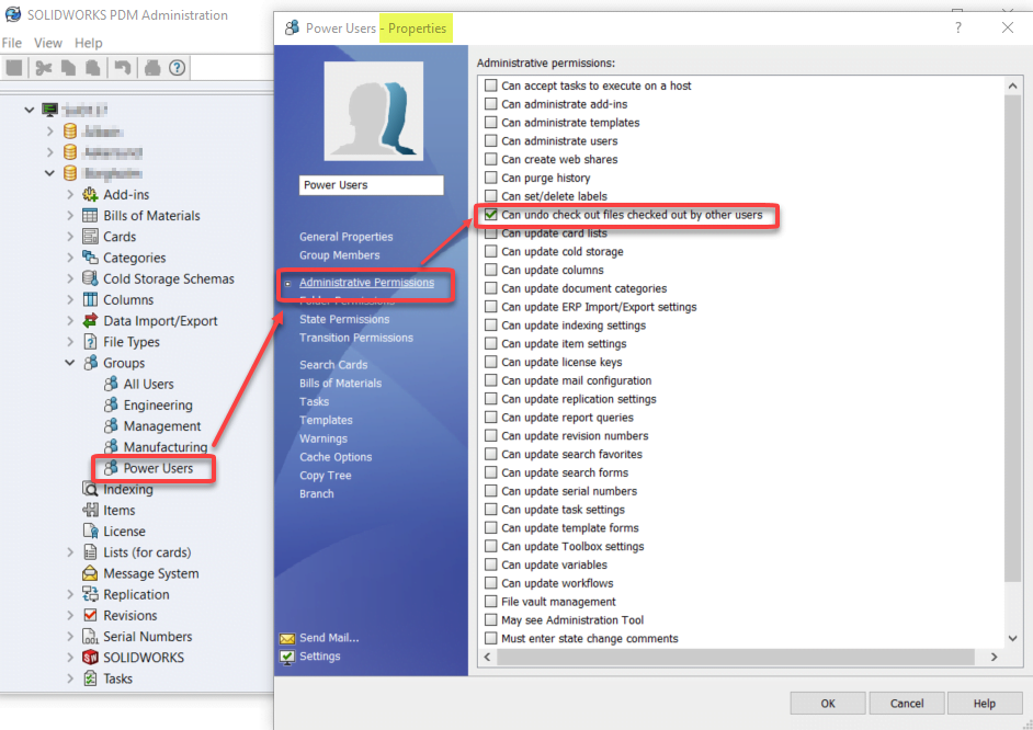
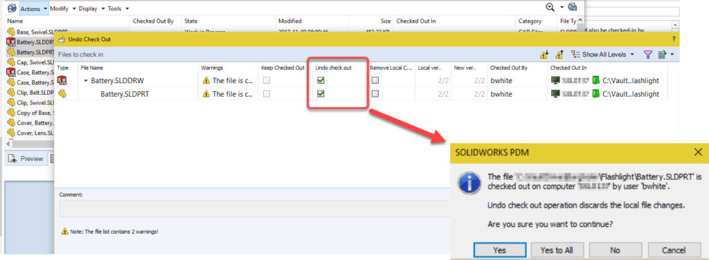
            PDM Administrators can now allow users to undo the ‘check-out’ of files checked out by other users! Permission was previously reserved for the default Admin user.

            The permission has been added to the Administrative Permissions under Groups — Users:

            No more files are stuck in ‘read-only’ when a user leaves for vacation!  No need to disconnect from the vault and log in as Admin to PDM.

            Even better, if the computer where the files are backed up is available, it is now also possible to archive files from another user profile. No more frustrated users returning from vacation!

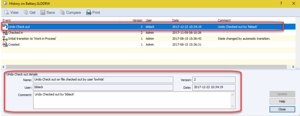
            To keep control of the possible chaos resulting from power abuse, a line has been added to the history containing all the details of the operation.

            X_green_halo

            Any questions? Need help? Ask one of our experts.

            Whether you’re ready to get started or just have a few more questions, you can contact us toll-free:

              Designing for Metal X 3D Printing

              BLOG

              Designing for Metal X 3D Printing

              [techtips_featured_image_shortcode]

              Metal 3D printing offers manufacturers a faster and more cost-effective way to produce strong, lightweight, and complex parts. With the Markforged Metal X printing system, businesses can replace certain casting and machining processes, consolidate assemblies, reduce material use, and accelerate production.


              However, successful metal printing requires more than simply sending a traditional CAD model to the printer. Wall thickness, supports, holes, threads, part orientation, and post-processing must all be considered during the design stage. In this guide, we explore the key design guidelines that can help you improve print quality and get the most from the Markforged Metal X system.

              Benefits of Metal 3D Printing with Markforged Metal X

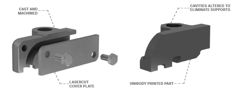
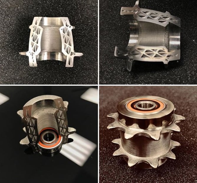
              However, for parts where casting or machining production methods would otherwise be used, producing through the Metal X printing system can be 50-90% faster and less expensive. In many cases multiple fastened pieces can be printed as 1 part, reducing assembly and maintenance time. Also, when the standard print settings are used, a printed part will often be 20% lighter than the same geometry produced by other methods.

              Metal X Design Guidelines and Best Practices

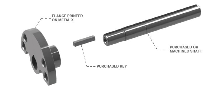
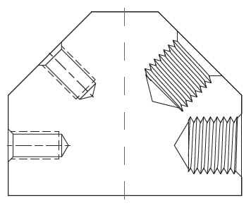
              Something to avoid is printing part features that could be easily purchased, such as shafts, threaded rods, pins, and similar mechanical hardware items. Additionally, the Metal X supports are fully solid and do not break or dissolve like plastic or composite printed supports do. There is a ceramic release layer between the support and the finished part geometry, however, it is still preferable to avoid as much support as reasonable. For external features, this is often accomplished by using 45-degree chamfers or tapers. For horizontal hole-type features, a teardrop or diamond shape will avoid the support that would have been used for a circular or square feature.

              As with any production process, there are some recommended minimum wall thicknesses and feature size dimensions that apply to Metal X printed parts. For structural soundness, the wall thickness of features should be 1.5 mm or greater, vertical holes can be as small as 1 mm, and grooves can be as thin as 0.5 mm.

              It is quite possible, and in many cases recommended, to print the threads of tapped holes rather than tap them after the sintering process. Vertical threads can successfully print as small as M3 or #5-40, angled or horizontal threads should be M10 or 3/8”-16 and larger.

              Post-Processing and Preparing Parts in Eiger

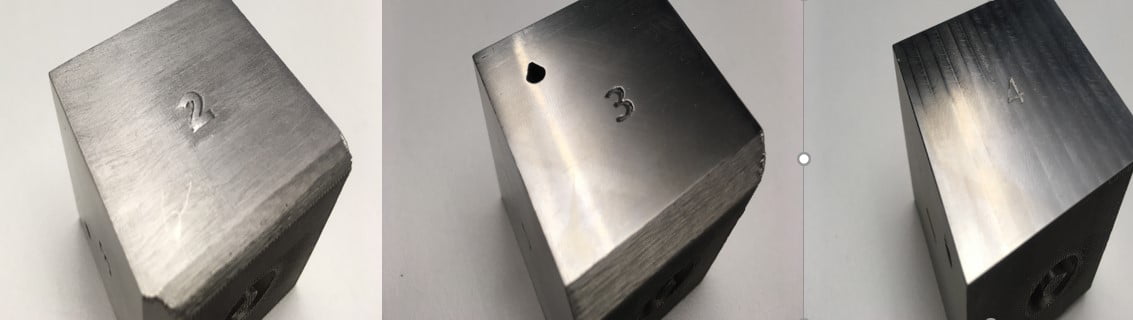
              Printed parts can be lightly sanded or smoothed with Scotch-Brite while in the green state condition to improve surface appearance. When using the standard settings, individual feature faces can be post machined 0.5 mm in the X or Y direction and 0.3 mm in Z to achieve specific fit conditions with other parts.

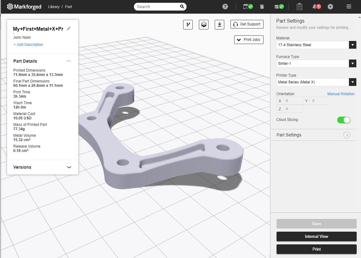
              Eiger does have some additional options for adjusting Metal X printing, particularly with regards to supports. However, it is certainly recommended to always use the [Internal View] mode to examine the part slicing in closer detail before sending it to the printer.

              Optimize Your Parts for Metal 3D Printing

              The Markforged Metal X system makes it possible to produce strong, lightweight metal parts faster and more cost-effectively than many traditional manufacturing methods. However, achieving the best results starts with designing specifically for the printing process.


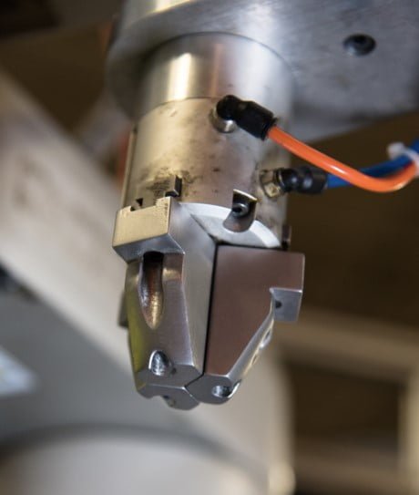
              By minimizing supports, respecting recommended feature sizes, optimizing hole and thread geometry, and reviewing each build in Eiger’s Internal View, manufacturers can improve print quality while reducing material use, machining, assembly, and production time. These design considerations help unlock the full potential of metal 3D printing for applications such as robotic grippers, tooling components, motor mounts, and powertrain parts.


              Contact the Solidxperts team to learn how Markforged Metal X can support your metal part production and help you identify the best applications for your business.

              X_green_halo

              Any questions? Need help? Ask one of our experts.

              Whether you’re ready to get started or just have a few more questions, you can contact us toll-free:

                Enhancements in PropertyManager in SOLIDWORKS Simulation

                BLOG

                Enhancements in Remote Loads/Mass PropertyManager in SOLIDWORKS Simulation

                [techtips_featured_image_shortcode]

                By Sakineh Orangi – Simulation Application Engineer at SolidXperts

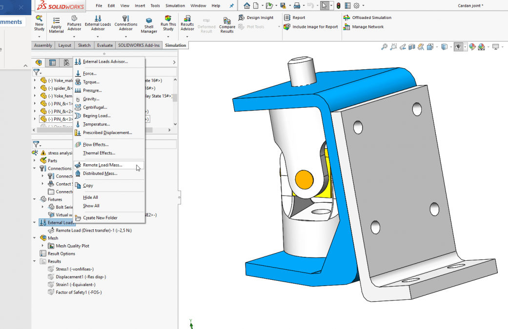
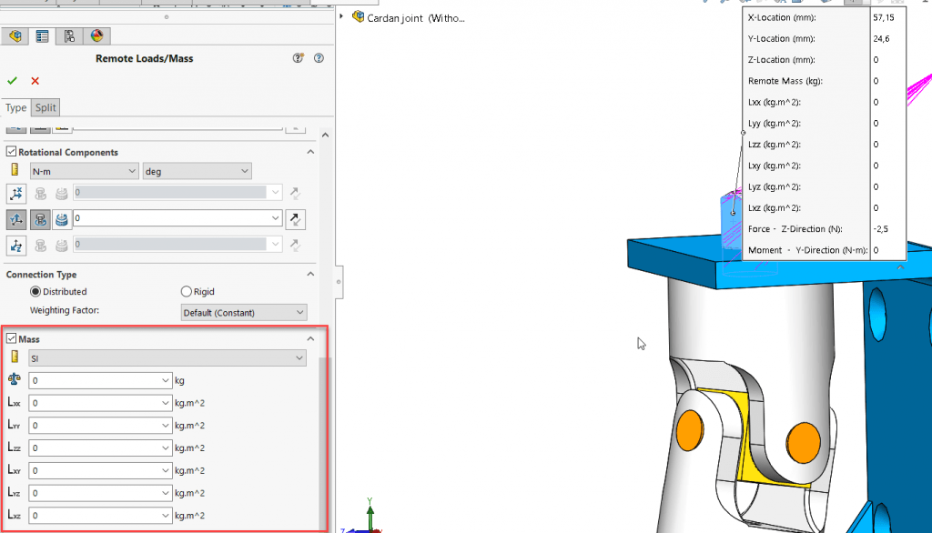
                In SOLIDWORKS 2019, the Remote Load/Mass PropertyManager was redesigned to improve the user experience and it introduced distributed coupling. The Remote Loads/Mass PropertyManager allows us to apply remote loads, remote masses, and remote displacements for static, topology, and nonlinear studies. One of the ways to access the Remote Loads/Mass PropertyManager is to right-click on External Loads in the simulation tree of linear static, nonlinear static, or topology.


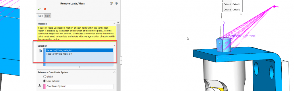
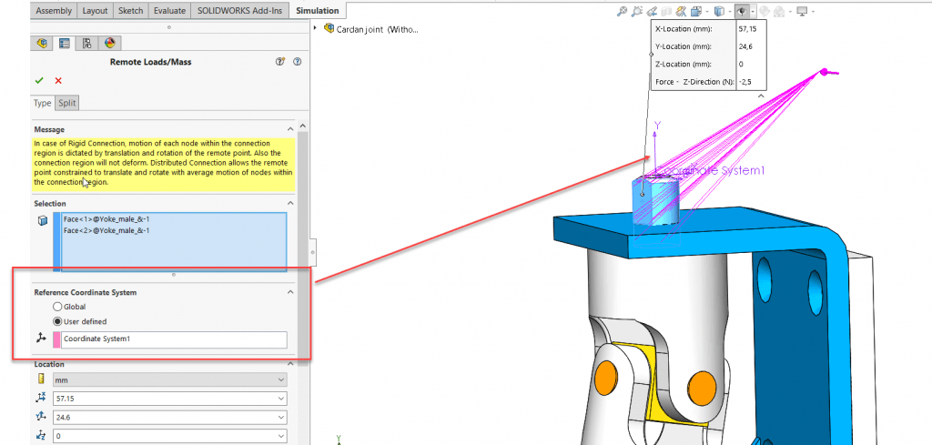
                We select the faces to apply remote loads, remote masses, or remote translations and/or rotations.


                We define the coordinate system used for the interpretation of the location and directions of the remote features.


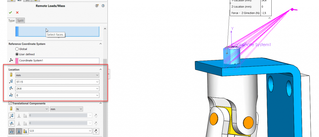
                After this step, we enter the coordinates of the reference node location in a local or global coordinate system.


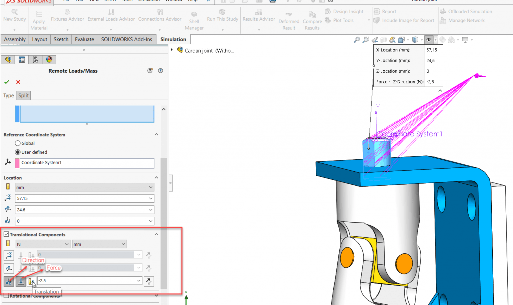
                In the case of the definition of remote force or remote distance, we check the Translational Components and enter the values of remote loads or remote translation in the three directions X, Y, and Z.


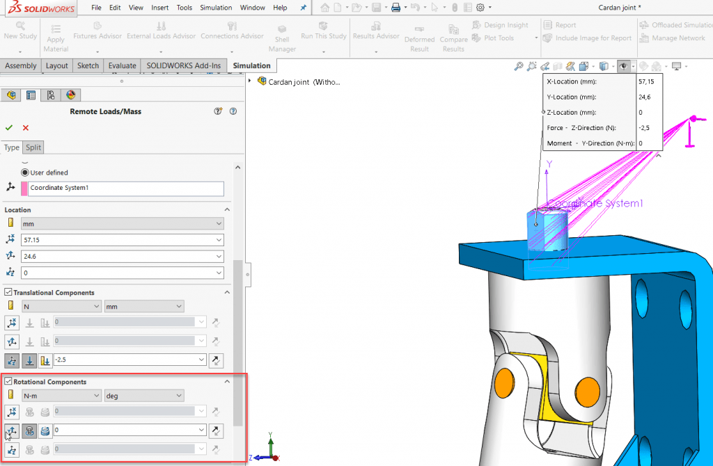
                If there are any remote moments or remote rotations, we check Rotational Components and then enter the data.


                 width=


                The connection type can be Distributed or Rigid. If there were several coupling points, we use Distributed coupling. For rigid connection, the coupling nodes do not move relative to each other. The faces where remote loads or displacements are applied behave like rigid bodies.

                The mass option is used to define components of remote mass. Data necessary for this option is the value of remote mass and moment of inertia regarding the axis of X, Y, and Z.


                Learn more about everything new in SOLIDWORKS from 2015 to 2019 by downloading our White Paper.

                To learn more about SOLIDWORKS Simulation, click here.
                X_green_halo

                Any questions? Need help? Ask one of our experts.

                Whether you’re ready to get started or just have a few more questions, you can contact us toll-free:

                  7 Essential Markforged Composite Features

                  BLOG

                  7 Essential Markforged Composite Features

                  [techtips_featured_image_shortcode]

                  written by Steven Murphy – Certified SOLIDWORKS Expert (CSWE)

                  Markforged transformed the 3D printing industry back in 2013 with the ability to create functional industrial parts. While this 3D printing powerhouse innovates with metal 3D printing, we want to take a moment to recognize the powerful features offered by the composite printers that keep them at the top of the FDM world. Here are our top seven Markforged composite features:


                  1. Fiber

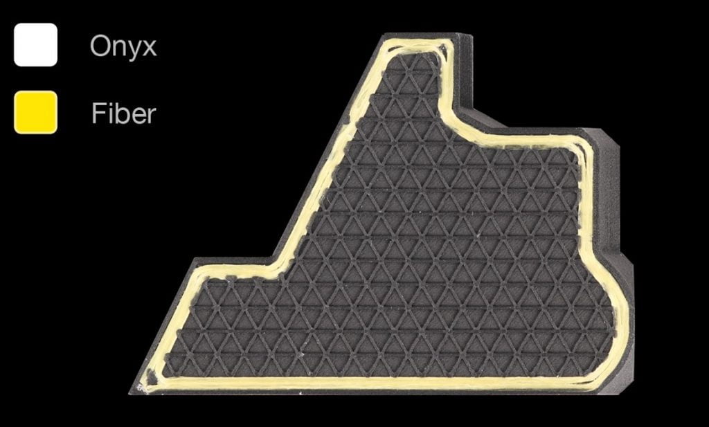
                  This is the go-to innovation for the Markforged printers – the ability to print with Continuous Fiber Filament (CFF) using Fiberglass, Kevlar, and everyone’s favorite, Carbon Fiber.

                  Impact:

                  3D printed parts 8x stronger than ABS with comparable traits to 6061 Aluminum unlocks design possibilities. Lighter parts with low cost and fast production can be a valuable proposition for many manufacturers. This feature single-handedly allows 3D printing to be a comprehensive solution rather than a prototyping tool.


                  2. Expand Thin Features

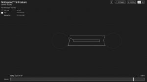
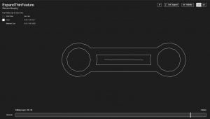
                  What exactly does “Expanding Thin Features” do? Enabling this feature will thicken your part geometry to meet the minimum wall thickness requirements of the printer. It will automatically take any layer that is too thin to print and  adapt it to meet the minimum requirements. Easily overlooked as it only takes one click to activate, you can see the part salvaged in the slice views below!

                  Impact:

                  This feature really excels at taking parts not designed for additive manufacturing and adjusting their geometry to be 3D-pintable. You need to be careful when using this feature as changing the geometry does not maintain the dimensional accuracy of the original CAD model. The major upside is that the majority of legacy parts can be printed on Markforged printers without any major redesign. This level of automation and intelligence is a huge jump in innovation in an otherwise stale industry.


                  3. Pause & Remove the Print Bed

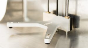
                  The print bed itself is fastened by three neodymium magnets, allowing the user to remove the build plate during any layer. This also means that you can replace the print bed and continue the print from where you left off. This process has a repeatability of 10 microns,  meaning there are no issues in continuing the print from the new position.

                  Impact:

                  Being able to pause and remove the print bed opens up many design options such as embedding hardware or enclosing secondary parts (eg. LED, magnets, or RFID). The repeatability and consistency of the print bed enables many tricks and are well documented in the Markforged blogs.


                  4. Adaptive Bed Leveling (X7)

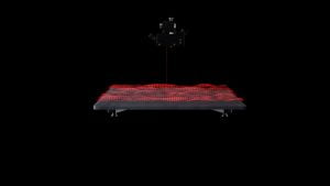
                  The X7 Industrial printer utilizes a built-in laser micrometer to create a contour map of the print bed with 1µm accuracy. While it will alert you to the bed not being leveled correctly, more importantly, the printer will dynamically adjust the extrusion of the first layer to increase the consistency of your print.

                  Impact:

                  The application of the laser measuring system eliminates many of the bed leveling issues that occur with standard FDM style printers. Not only are the parts flatter than traditional FDM printers, but the initial compensation means significantly fewer failed prints.


                  Bonus: Blacksmith

                  Check out the Blacksmith AI that takes advantage of the same laser micrometer to adjust the physical part based off of inspection results. The end result is a tight feedback loop that makes extremely accurate parts that become more accurate over time.


                  5. Turbo Print & Turbo Supports [BETA Features]
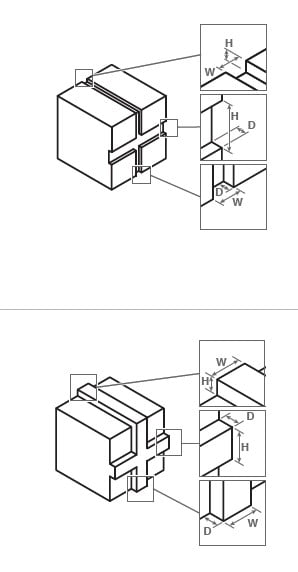
                  The Turbo BETA features allow for support and infill to be printed at twice the layer height of the print. By taking advantage of the support structure, Markforged has increased opportunities to save time and material on your prints.
                  Impact:

                  The turbo features allow for faster print times and reduces material. Fundamentally, it shows that Markforged is committed to improving and implementing solutions. They are willing to continuously improve their product, and will continue to add BETA features.


                  6. Eiger Dashboard

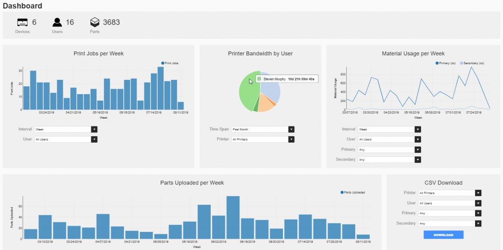
                  With a versatile cloud based software, there many metrics tracked for your convenience. The Eiger Dashboard allows for both management and users to track printer statistics such author and material usage.  Not only does the portal include integrated graphics, but the data is also available as a CSV.

                  Impact:

                  In traditional manufacturing, material and time management are a huge part of resource management. Using Eiger, it is incredibly easily track material usage, up-time, and other valuable metadata to make your operation more efficient.


                  7. Eiger Internal View

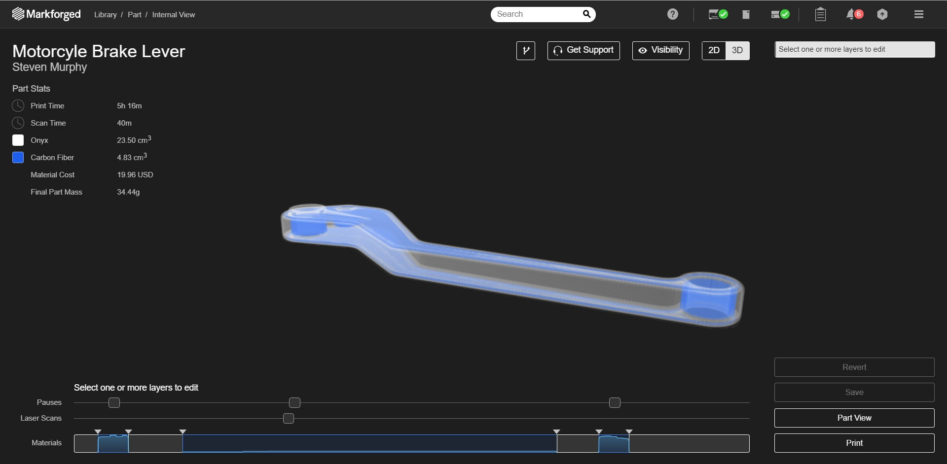
                  With the Eiger “slicer”, users can view the internal features of your part in both 2D and 3D. These views also include the thermoplastic structure, infill, use of fiber, and removable supports. Additionally, the slicing view includes a live slider, which reflects print time and material usage by layer. The best feature when using the internal view is the ability to add and adjust fiber layers (blue sections).

                  Impact:

                  When enabling fiber usage in Eiger, the standard automation of fiber reinforcement does an exceptional job. However, the ability to control fiber layer placement gives you, the user,  the option to add strength to the part without overcompensating with fiber or increasing unnecessary part cost. With clever orientation and fiber layouts, you can create very strong, yet cheap parts! Need bolt holes strengthened to resist shear stress? No problem! Want to take advantage of beam bending theory to reduce cost? Takes only a few clicks. This adaptability and maneuverability in the internal view make this one of the highest impacts features with the Markforged printers.

                  Try Eiger for free! 


                  Conclusions:

                  So there you have it – The key features Markforged composite printers have to offer. Even though FDM style printing is a known quantity, Markforged has managed to innovate on key features that keep the technology fresh.


                  For more information, contact an Xpert today!

                  X_green_halo

                  Any questions? Need help? Ask one of our experts.

                  Whether you’re ready to get started or just have a few more questions, you can contact us toll-free:

                      Download

                        Download

                          Download